 |
|
Welcome to my personal Radio Canada International Website and please enjoy the tour! My wife, Gretchen and
I took all photos on these pages. Please click on pictures to view larger 640X480 versions. I am not affiliated
with RCI, but for further information and questions directed to CBC or RCI, please Visit the official
|
Many thanks to David Horyl, assistant plant manager for the tour which resulted in these photographs
and information |
|
|
|
|---|
|
Graphic illustration of how output envelope wave (blue) is produced by pulse-step input (yellow). |
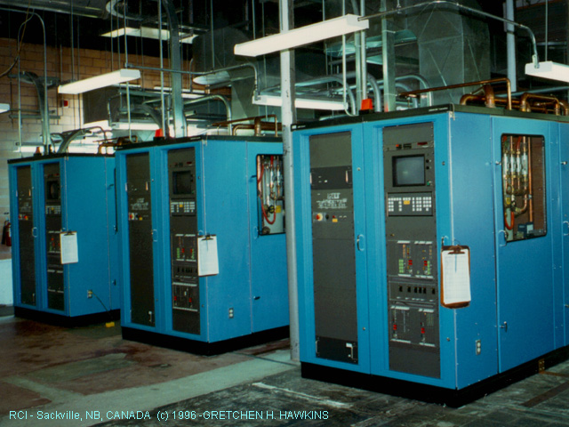
| Three 100KW Harris transmitters use a pulse width modulation technique to achieve AM. The third set are three Collins, 250KW transmitters using High Level plate modulators transformer coupled to the RF units. The whole facility is controlled by computer automation which is centralized in the main control room. Frequencies, antennas, and input feeds are switched all according to internatinally agreed upon schedules which are renegotiated twice per year with other countries. Much of the software is developed by programmers and engineers on the site. |
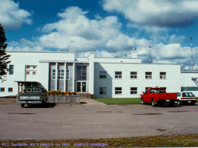
The site at Sackville was originally built in 1938 for CBA for local broadcast. In 1943, two RCA shortwave
transmitters were installed. In 1970, CBA was moved out to Moncton,
NB to make room for the Collins Transmitters. In the mid 1980s, the RCA transmitters were replaced by the three,
more modern, Harris transmitters.
|
|
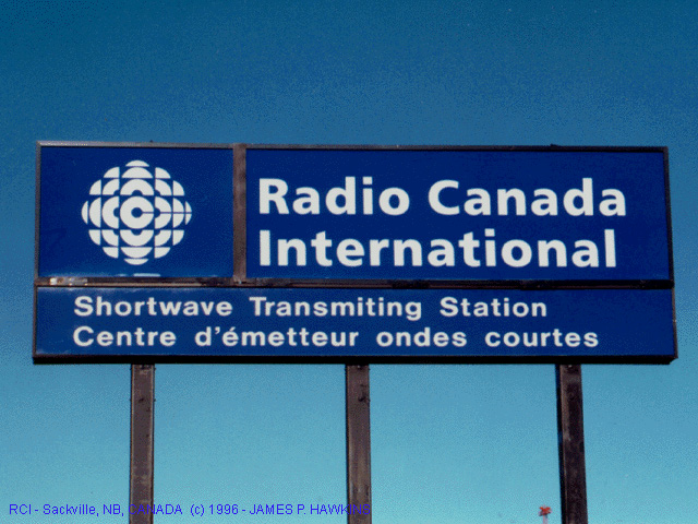
Closeup view of sign along Trans Canada 2 only a few miles from the Nova Scotia border. |
|
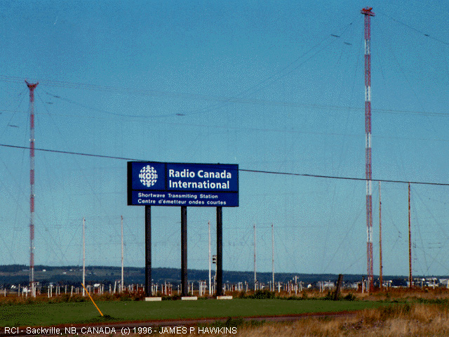
Wide view of sign showing part of vast antenna farm in the background. |
|
|
|
|
|
|---|
|
|
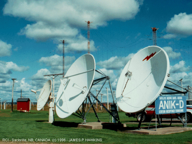
These dish antennas receive the input feeds from Montreal via Satellite. This facility is also used for Radio Japan, Radio Beijing, BBC World Service and Radio Korea as part of an exchange agreement. |
|---|
|
|
|
|
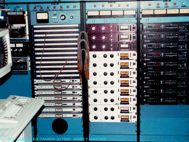
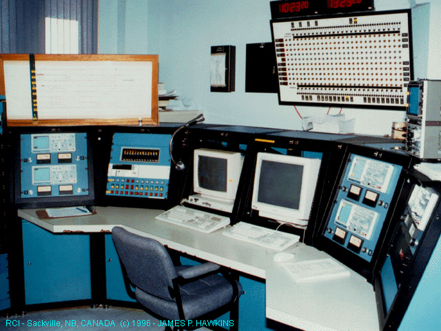
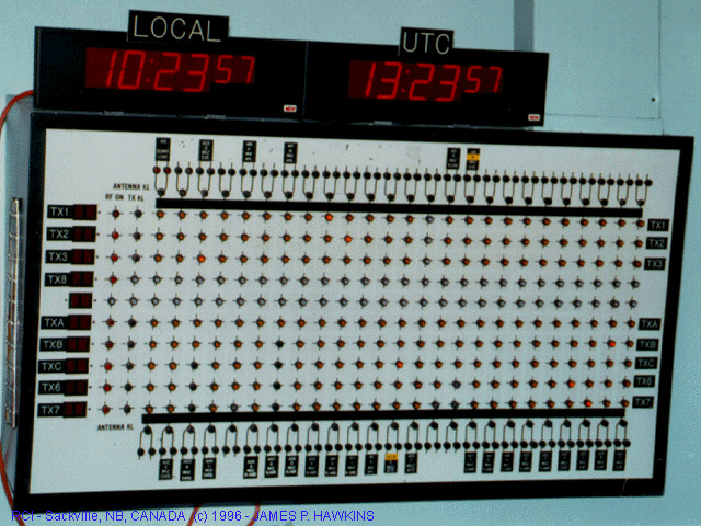
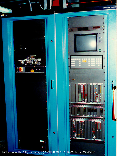
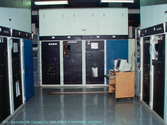
| Control panels for incoming audio feeds. | Central Transmitter Control Console | Antenna Switch Matrix Status Indicator Panel which clearly shows transmitter to antenna connection configuration. |
|
|
|
|
|---|---|---|
|
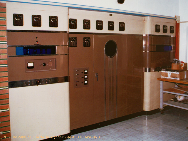
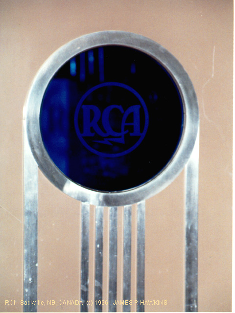
Center portion of RCA 50T transmitter used in earlier CBC days with that wonderful ART DECO look! The building used to house live studios, also. The transmitter is no longer in use. There were additional sections to the right and left of this at one time. |
Close up of the center door on the transmitter. |
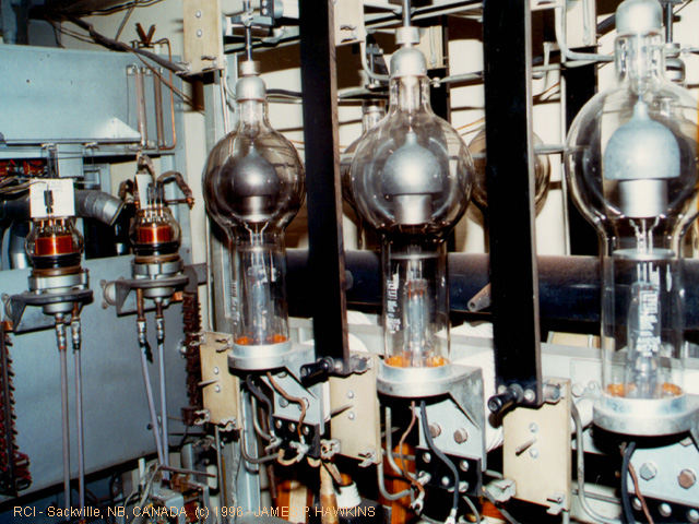
We took a walk through that center door into the transmitter and we find an array of huge 857B HV rectifier tubes! I believe there were eight of them, each about 18" in height! My wife, Gretchen, myself and David Horyl all fit in this compartment, but, I'm glad I had a wide angle lense. |
|
|
|
|
|---|---|---|
|
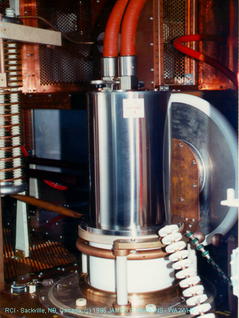
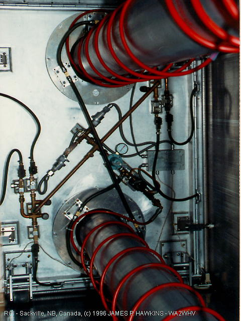
View of Steam Cooled Final RF TUBE type CKQ350 in ABB Unit, manufactured by Thomson Tubes in France. Note, coolant inlet and outlets at the top of the tube. |
Three ASEA BROWN BOVERI 250KW RF UNITS |
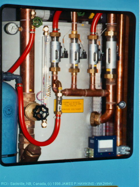
View of Cooling Control plumbing in RF UNIT. |
|
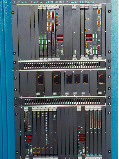
Closeup of ABB Transmitter Panels |
|
|---|---|
|
|
|
|
|
|
|
|---|---|---|
|
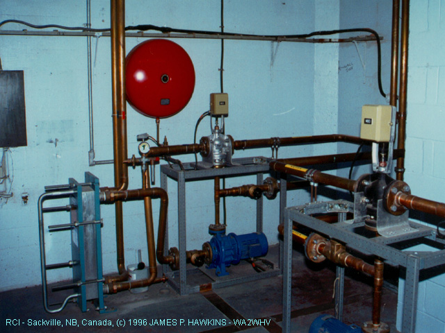
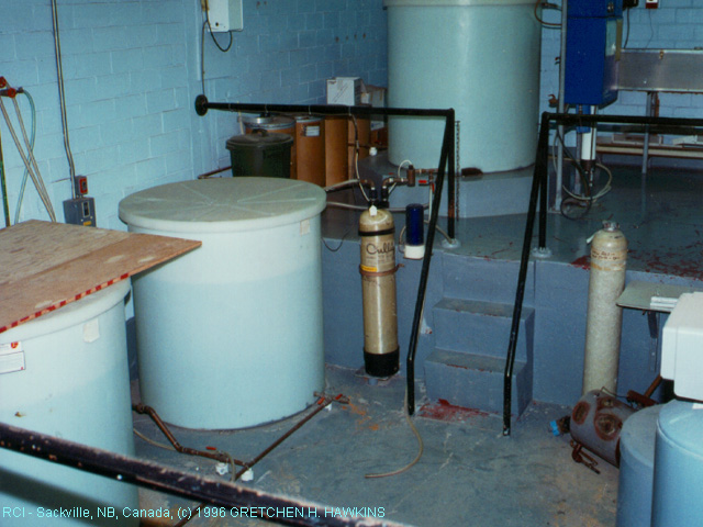
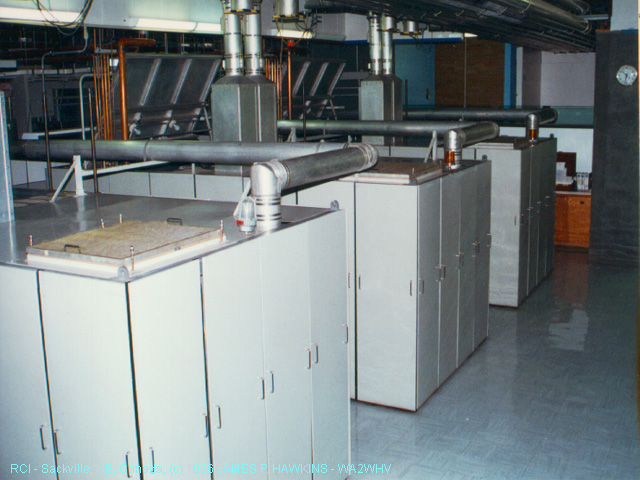
Heat exchangers and cooling pumps. Glycol is used to cool the water. Large red "bell-like" object is an expansion tank. |
Water purification system. |
Solid State Pulse-step AM modulator, 24 PSM modules. |
|
|
|
|
|---|---|---|
|
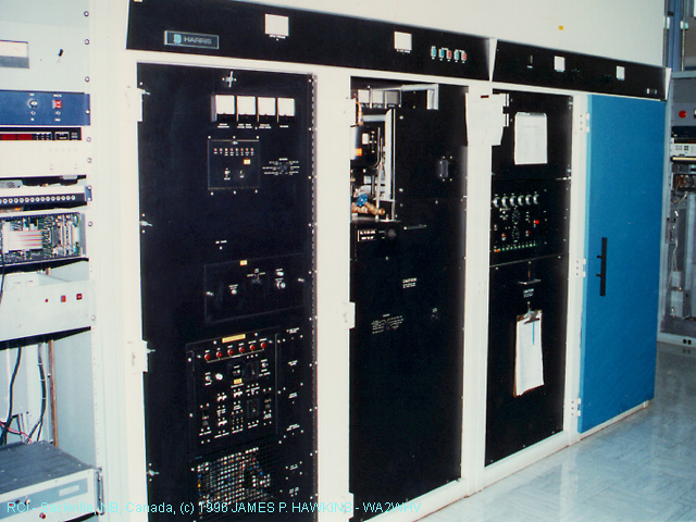
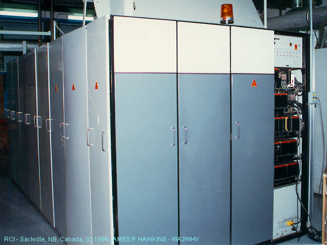
Wide view of three 100KW Harris Pulse Width Modulated AM Transmitters. The final tubes are type 4CV100000Es. |
Angle View of one of the Harris units. |
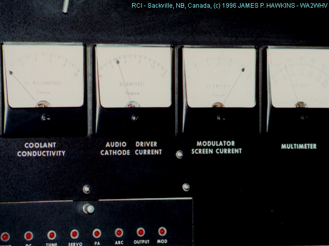
Closeup of some of the metering. Note that coolant conductivity is monitored. |
|
|
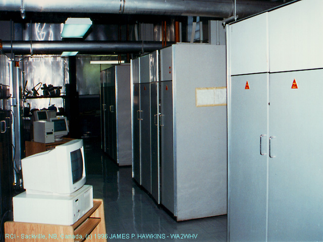
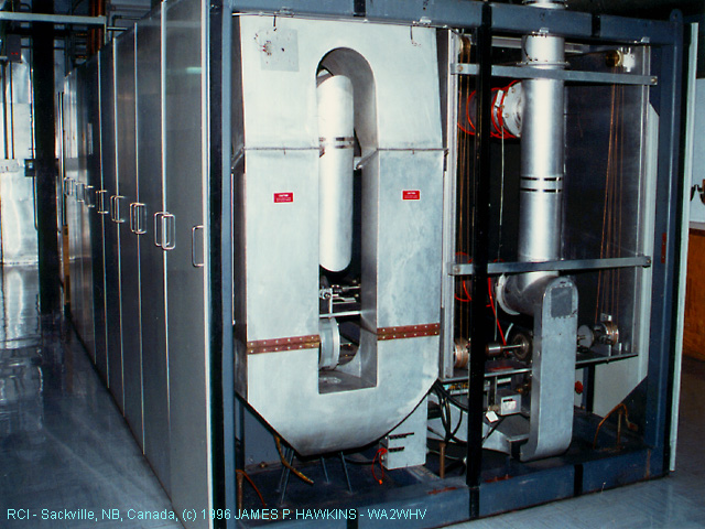
Overhead view of three 250KW Collins RF Units. |
|
Front view of Collins RF Unit |
|---|---|---|---|
|
|
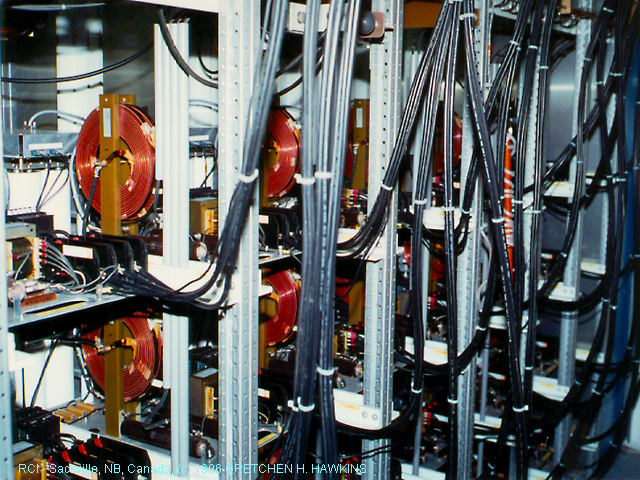
View of Corresponding High level Collins amplitude modulator Units (RF Units are lined up on left). |
|
Rear view of open back end of Collins RF unit showing tuning cavities. |
|
|
Closeup view of Collins tuning cavity. Far wall slides forward and backward to change the inductor length. They are tunable from 4.0 to 26.0 MHZ. |
|
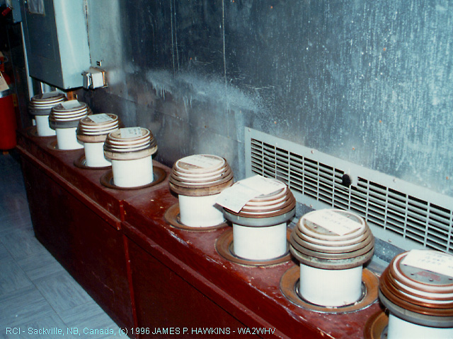
Storage area for final tubes, type 4CV100000C, for Collins Transmitters. Each weighs 90 lbs. The Harris transmitters use type 4CV100000E. |
Click here to hear the "ROAR" of the Collins transmitters.
Turn the volume up so you can't hear much of anything else to get a realistic idea!
|
|
Modulation transformer for Collins 250KW transmitter. Click here to hear what the transformer in this scene sounded like when the photo was taken. You are hearing approximately 15,000 volts of audio swing. (Needs "Real Audio" player) |
|---|
|
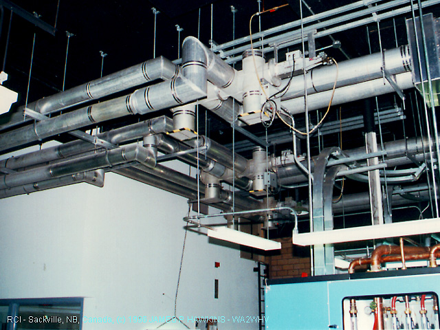
Looking to the ceiling, mazes of coax on their way to the switching matrix. The coax is constructed using eight inch pipe with standard 1/2 in. copper water pipe as an inner conductor spaced with Teflon insulators. It is made on site. |
|
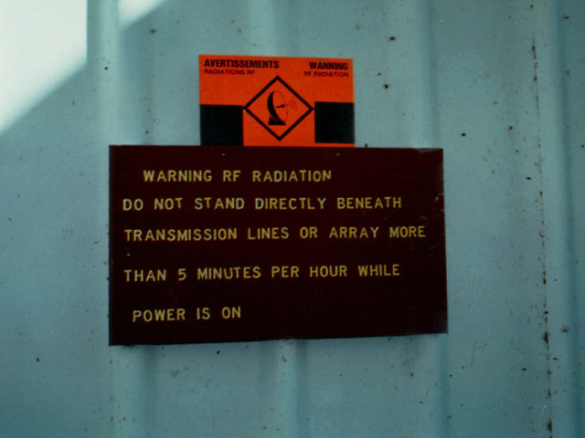
Standing under the huge bundle of coax ducts, connecting to the switch matrix building is this sign. |
|
|---|---|---|---|
|
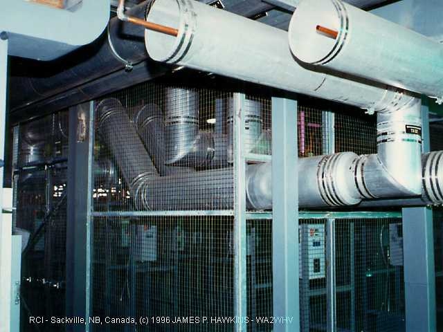
Coax coming into the switch matrix building. |
|
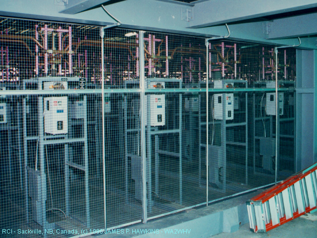
Inside the switch matrix building. This switching matrix is computer controlled. |
|
|
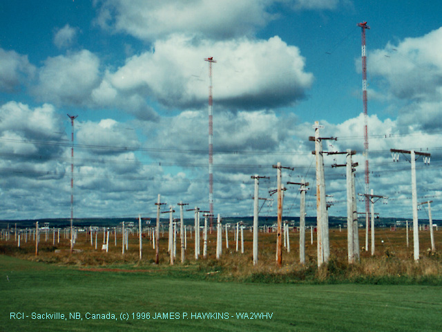
RF goes out to the antennas in parallel open wire pairs. |
|
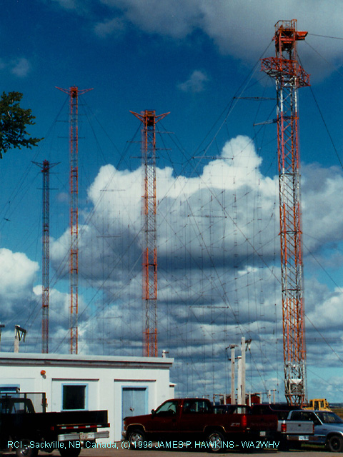
Nice shot of towers supporting stacked dipoles. The radiation direction from these dipoles can be changed about 13 degrees either way from perpendicular by phase control. |
|
|
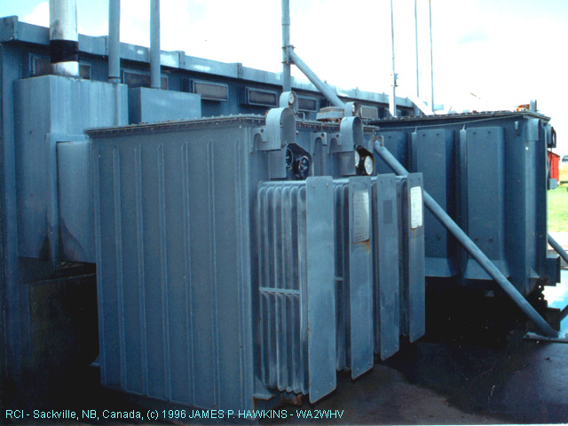
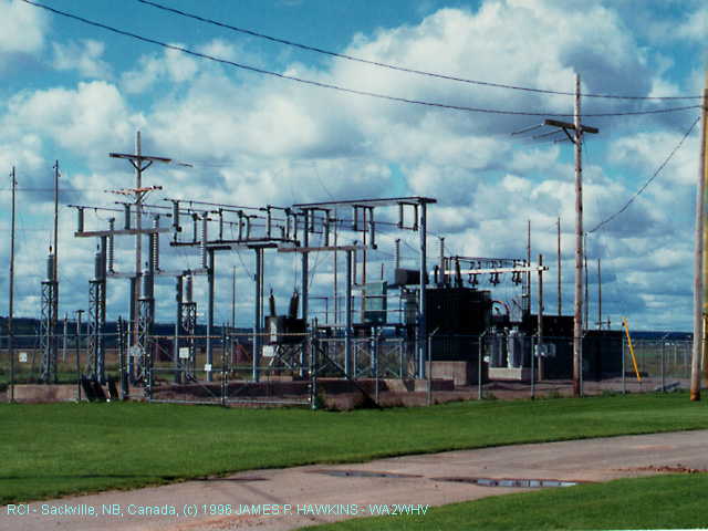
Power substation for the site. |
|
|---|
Accessed times since October 1, 1996.
All images are Copyrighted and are provided for your personal enjoyment.. Contact: Jim Hawkins