 |
|
See five part, 40 minute YouTube.com video HERE |
I am not affiliated with VOA. For further information on Voice of America, Please Visit the VOA OFFICIAL WEBSITE
| Many thanks to Carl Lineberger (WA4TEP) for the tour which resulted in these photographs at Voice of America Transmitter site 'A' near Greenville, N. Carolina. I am also grateful to other members of the technical staff at Greenville for commenting on this Web page and sending me more detailed information about the pictures. Jim Hawkins - WA2WHV. |
|
|
|
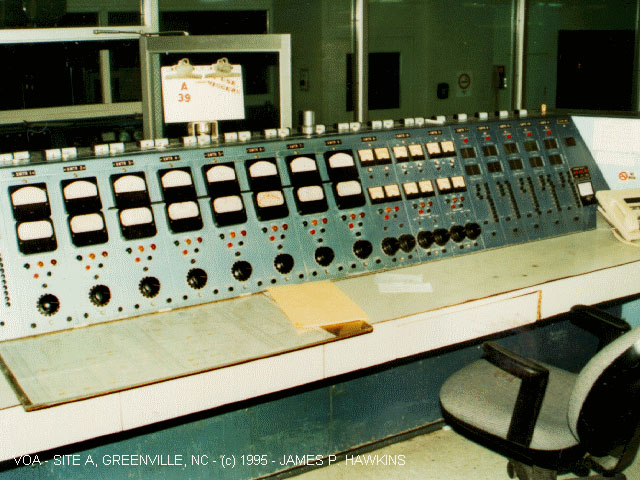
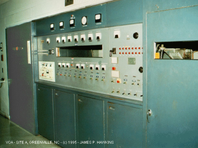
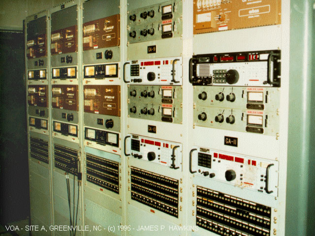
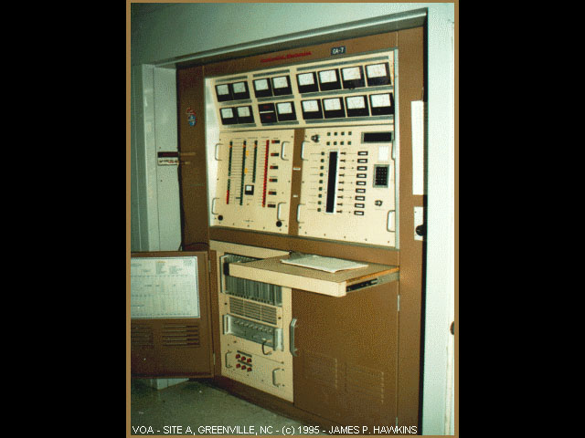
Central Transmitter Control Console |
|
|
|
|
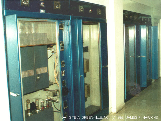
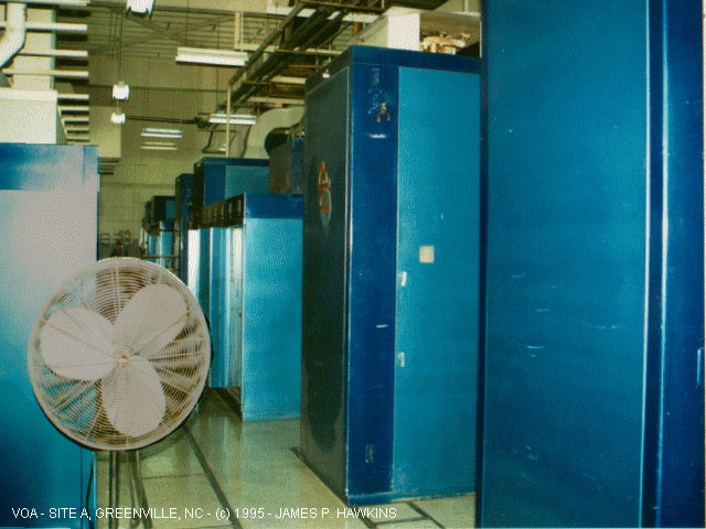
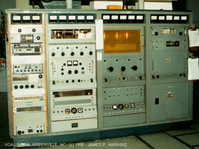
| On the left are front panels of Continental Electronics 500KW transmitters built in the 1940s, still in use. Each is a pair of 250KW transmitters combined. The center photo, taken in back of the front panel unit shows the huge cabinets housing the rest of the transmitters. On the right is a central control panel for these transmitters. Note the dials which were of the type found on old National receivers. There are 3 pairs on the site. |
||
|
|
|
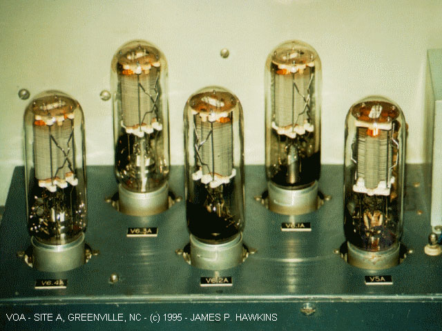
Type 845 modulator tubes. This tube type |
| The old Continentals use low level modulated Doherty amplifiers. The 845s shown above modulate a pair of 807s. The modulated RF signal from the 807s drive a single 4-400A which drives a pair of 4-1000As in the front cabinets. This modulated RF signal drives a Doherty amplifier which contains a "carrier" tube and a "peak" tube. |
|
|
|
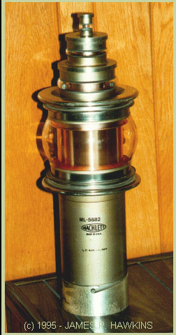
5682 |
|
|
|
|
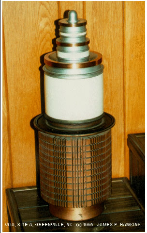
This GE 4BT250A transmitter was |
Vapor cooled tube used in |
 |
Continental Electronics Model 420B-1 500KW Transmitter featuring high efficiency pulse width modulation. This unit is actually a prototype. |
|
|
|
|
Transmitter front panel |
Thomsen TH-558 |
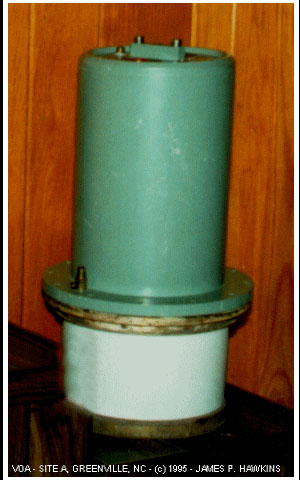
| Marconi B-6127, 500KW transmitter. The original, 2-tube, pulse width modulator was removed and replaced with a solid-state modulator, made for VOA by Continental Electronics. The solid-state modulator (SSM) is capable of both SSB and AM operation. On the right is the single, water cooled final tube used in this transmitter. Note the water inlet and outlet on top of the tube. This tube and transmitter is discussed in Monitoring Times, September 1995 on page 28-29, Article "VOA's Tangier Relay Station". |
 |
| Technical Material Corporation GPT-40K. All-mode transmitter USB-LSB-ISB-AM-FSK-FM. Basically a Harris exciter, driving 10KW amplifiers that drive 40KW amplifiers. This transmitter is run in the ISB mode, with the carrier suppressed 16 db. The carrier is there to allow the AFC circuits of the special VOA ISB receivers at the overseas relay stations to lock precisely on the correct frequency, so the recovered audio doesn't sound like Donald Duck. |
|
|
|
|
|
Huge antenna matrix switch. |
One of many Sterba Curtain antennas |
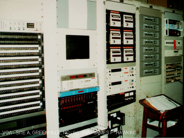
Equipment rack, including Optimod Audio Processors |
|
|
|
|
|
Satellite receivers. |
Audio Switching and control. |
Frequency Synthisizers. This is where the radio signal begins for each transmitter. |
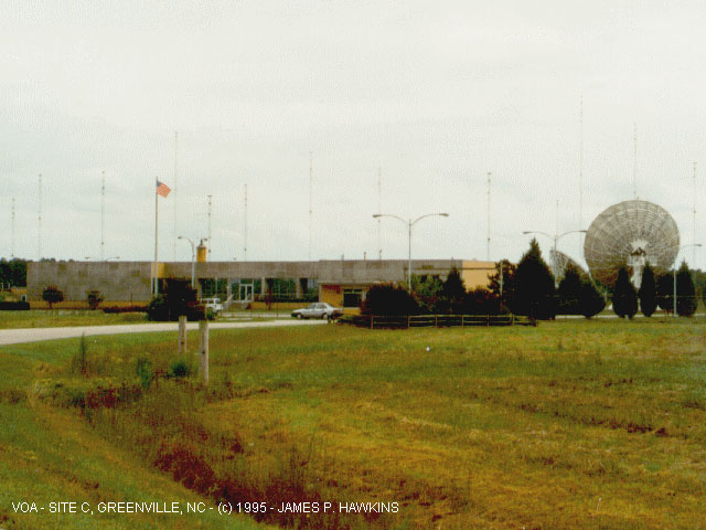 |
| Shown above is the recently closed Site 'C' Receiver Plant. Note the 13-meter C-band dish that was abandoned
when the satellite site was moved to site A. Site 'C' was the Master Control audio switching center. Programs were received from Washington via a Washington to Greenville microwave link (7 unattended repeaters between Greenville and Washington). Operators ran manual console switching programs to Site 'A' and Site 'B' via intersite microwave systems. 'C' Site also had about 8 RCA SSB-R3 dual diversity independent sideband receivers that were used for receiving other broadcasters. Audio was sent to Washington on the microwave so they could record and monitor. The antenna field was (is) full of pairs of rhombics spaced to provide dual diversity inputs to the RCA receivers. A "torn-tape" RTTY was run at the comm center for RTTY skeds with all the relay stations (AFSK on the TMC transmitters) each day for schedule updates and administrative matters. Plant 'B' exists and transmits only during an 8 hour shift that spans the normal 4pm-MN and MN-8 time periods. Plant 'B' is the same size building as Plant 'A'. More or less the same transmitter arrangements. 3 500 KW 420A (GB-1,2,3) 3 GE 250 KW (GB-4,5,6) 1 BBC 500 KW (GB-7 versus the Continental 420B GA-7) 1 AEG 500 KW (GB-8 versus the Marconi GA-8) 1 50 KW ISB Continental 617A (GB-9) 2 40 KW ISB TMC (GB-10,11) |
| Accessed | times since January 1, 1996. |