|
|
Location Map
See new embedded YouTube video of Greenbury Point Tower Demolition
|
|
Location Map
See new embedded YouTube video of Greenbury Point Tower Demolition
| The original construction of the Annapolis Radio Station, which became NSS. It consists of photographs of the Poulsen Arc transmitters in 1918 and other apparatus. The photos are very clear, having been scanned from the original large negatives. Construction of one of the towers is also shown. |
|
ACNOWLEDGEMENTS I'd like to thank Steve Ickes - WB3HUZ, webmaster/designer of the AM Window website, without which I would never have known about the NSS tour. Be sure to visit his site, it's well worth it! Thanks to John Cummings - N3CZE, who coordinated the tour, Bill Smith - N3SZW, for supplying directions to the site, Bob Koonce - W3GOU (former supervisor of communications at NSS) for an excellent presentation of the transmitter operation at the beginning of the tour. John Short, antenna expert at NSS; Craig Shuck; and Norm Chipps - N3RZU, AMer, vintage and military radio enthusiast. If I've left anyone out, mispelled any names or if anyone knows the names of all the tourguides and their function at the station please send me e-mail, so I can acknowledge them for their efforts on the tour and service at this facility. If it's YOU, please don't be shy, toot your horn. :-) Also, please feel free to send me mail on information you may feel is inaccurate or important additional information that may be worth mentioning. I do have other photos, but server space is running short. 73, All images are Copyrighted and are provided for your personal enjoyment. Use of these images
for commercial |
|
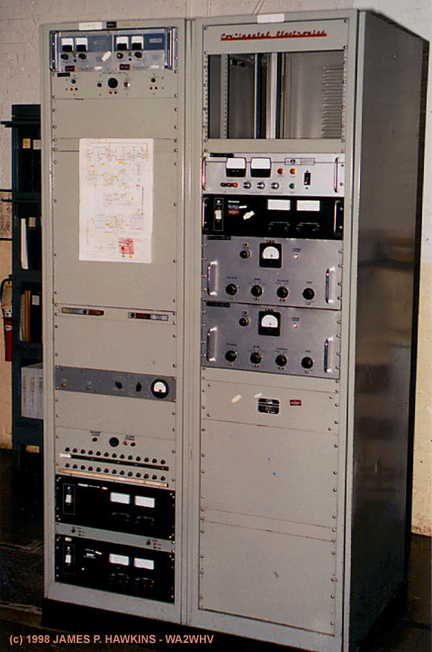
Transmitter Exciter and Console |
|
|
Crystal Oscillators/Exciter - Generates low level the signal used by the transmitter. |
|---|---|
|
|
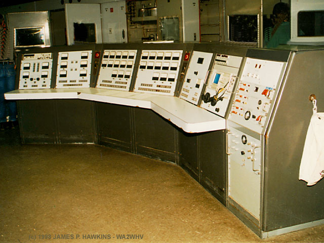
Central Control Console. The signal from the exciter passes directly to the console at the millivolt level. The console monitors and controls all stages of the transmitter. |
|
General Operation This text was derived from the presentation given by Bob Koonce. The Continental Electronics AN/FRT-87 One Megawatt VLF transmitter consists of two separate power amplifiers and two intermediate amplifiers or driver units. In normal operation, both PAs are used, but only one driver is used at any given time. PA voltage is normally 18KV. The combined output of the to PAs together was 830KW. Each amplifier was capable of 550KW, power was lost in the summing of the two. PA tubes were direct contact, water cooled tetrodes (type unknown). The radiated output was 30KW. The panels on the console are organized in a fashion that follows the amplification stages from left to right and allows tuning, monitoring and control of these stages. The IPA (Intermediate Power Amplifier) controls are on the far left. The signal is run through three stages of amplification, the final stage consisting of two 4CX15000 power tubes in a push-pull AB2 configuration. The output of the IPA was between 1200-1300 watts, which would drive the two final amplifiers. Tune-up was accomplished one amplifier at a time. After each amplifier was tuned individually, the outputs were "married" together in parallel. So, you have two power amplifiers, whose outputs are in parallel and whose inputs are driven by one, common IPA. Each PA contained three tubes. Two were in use at any given time with the third being a "hot" standby. The output of the amplifiers would pass through a network of capacitors and variable inductors (variometers) to a gigantic toroid (a tall configuration with metal slats around it). The toroid ties the output of the two amplifiers together in parallel into the transformer primary. Through the center of the toroid runs a single "litz" cable, which acts as the transformer secondary. The cable then passes into and up through the roof of the "Helix house." From the top of the helix house, three feedlines pass to a quarter wave Marconi (vertical) antenna. That is, it's supposed to be! But at 21.4 KHZ, the wavelength is about 8 miles! The actual tower, of course is only 1200 feet. So, to make the antenna appear to be the correct length to the transmitter, a huge capacity top hat is employed. This technique was copied from the Russians (see note). The antenna that this was copied from is called the Goliath antenna. So the overall antenna at NSS is called a Modified Goliath Antenna. The top hat (a radial of cables) weighs as much as a destroyer, according to Bob Koonce. With the three feedlines, the feed impedance to the antenna is 0.1 ohms! The feed going out to the antenna is actually part of the antenna! So, when you tune the variometer, you are actually tuning the antenna itself. Typical tunup time was 20 minutes. Tuning the amplifier was a complex procedure to get the individual amplifiers to put out the same power in "mark" or "space" mode. Bob Koonce explained this in great detail and for now, I won't include it all here. (I have it on tape. Do you really think I could have remembered it? :-) One notable thing was that during high wind conditions, with the antenna system being the exremely high Q that it was, operators would have to sit in front of the controls and continually trim as the system changed. I'm sure that if this system were designed today, this would be computer monitored and controlled.
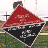
The mode of transmission was FSK (Frequency Shift Keying) at 25HZ at a rate of no more than 50 baud. If the FSK exceeded 50 baud, the insulators at the end of the top hat would arc because of the extremely high Q of the antenna (the bandwidth extended too far beyond the point of peak tuning). The RF environment in the area of the antennas was extremely dense at all times as this sign in back of the Helix house warns.
|
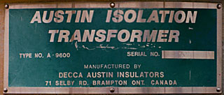
| A Note from Ed Phillips - W6IZJ Goliath was a GERMAN system developed during WW2 for communication with subs. For some reason or other I think it was located in Denmark, but that my be faulty memory. The Goliath antenna was of considerable interest in that, due to the shortage of copper in Germany at the time, all of the antenna cables and ground radials were made out of galvanized steel! A full description of this antenna is contained in VLF Engineering, by Watt. |
Transmitter Front Panels
Left PA Panel
Aisle between left Right PA Panel
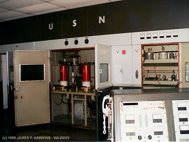
and right panels showing
water pipes and guages.
|
Two Functionally Identical (but reversed) Panels of the Continental Electronics The front of the transmitter has a 'U' configuration which spans across the entire control room. Between the two PA panels is an aisle accessing other components of the transmitter on either side. At the far end of the aisle is a control panel for the water cooling system. On both left and right extreme ends, the cabinet doors open up to long aisles on either side of what is a huge tuned circuit beginning with an aggrigate of capacitors, then huge, wood framed, tunable inductors called variometers. The output is combined in parallel into an enormouse toroid at the end of the chamber. A single heavy cable runs up through the toroid as the secondary which leads out to another very large room (Helix room) eventually to a feed out of the top of the building to the rest of the antenna system. There is no transmission line. The antenna system begins at the toroid, there is, therefore, no SWR! |
|
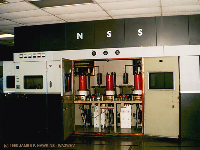
|
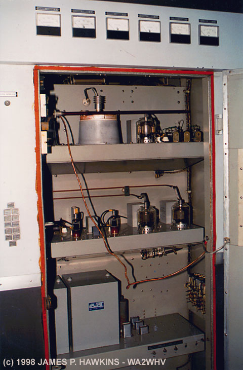
Open cabinet of intermediate amplifier. There are two of these cabinets, one on each side of the transmitter. Only one is used at any time. Two 4CX15000 on the top shelf left side, sitting in air- cooling chimneys. |
|---|---|
|
|
Three Eimac tetrode PA tubes. Only two are used at a time on each side of the transmitter for a total of four at full power. |
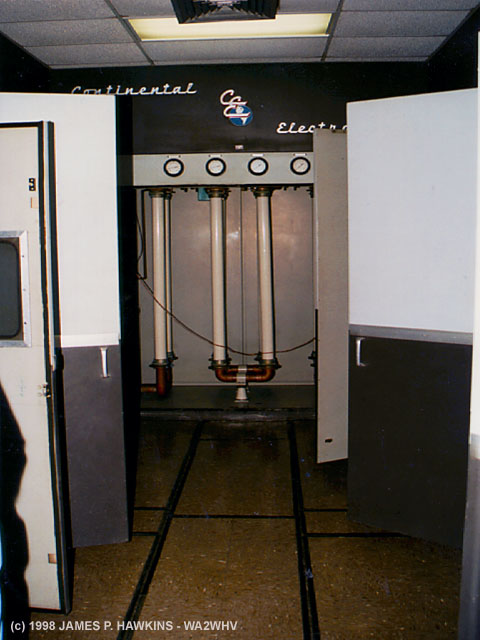
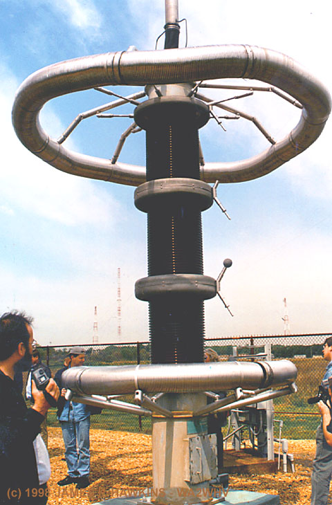
Tank Circuit
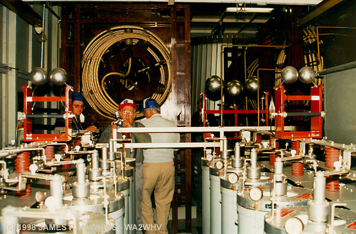
View of Tuned Tank circuit room. Gas filled capacitors
(each, 25,000 pF and 52 kV peak) are in the foreground, tank
coils right behind and at the far end is the tall toroid
(surrounded by vertical strips.) Some other visitors in
the picture make the scale of these components more
apparent. Discharge balls (to handle lightning or mis-tuning)
are also visible.
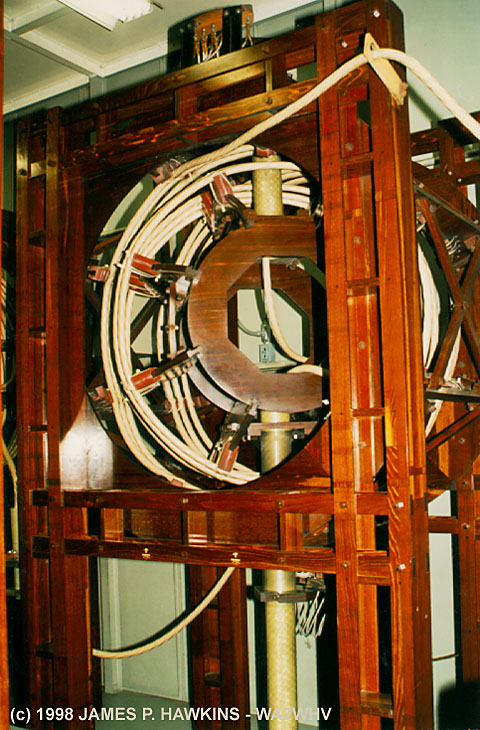
View of one of the variable inductance coils (variometers), all
mounted in beautiful varnished hardwood. The center of the
variometer rotates which varies the inductance by virtue of
its relationship with the outside winding from an opposing to
aiding mutual inductance.
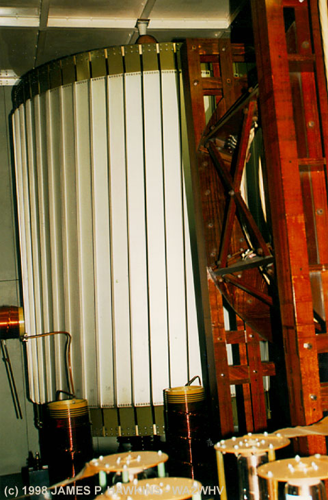
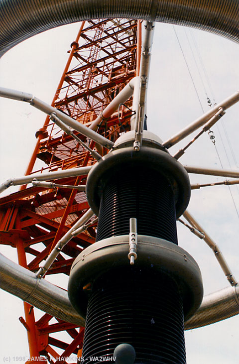
The toroid is fed by the tank circuits of both PAs in
parellel. It reminds me of Madison Square Garden.
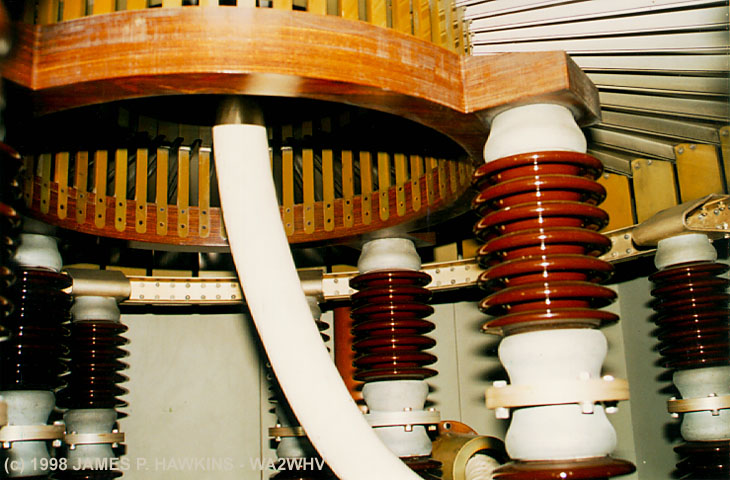
Heavy, single "litz" cable runs down through and out
of the toroid, on its way out of the building. This litz cable
was used throughout the entire antenna system. Each cable
is made up of over 100,000 insulated strands of fine wire.
The output wire goes out of the building through the roof
of the helix house.
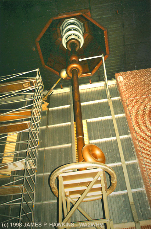
Out to Goliath
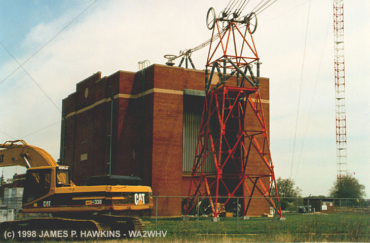
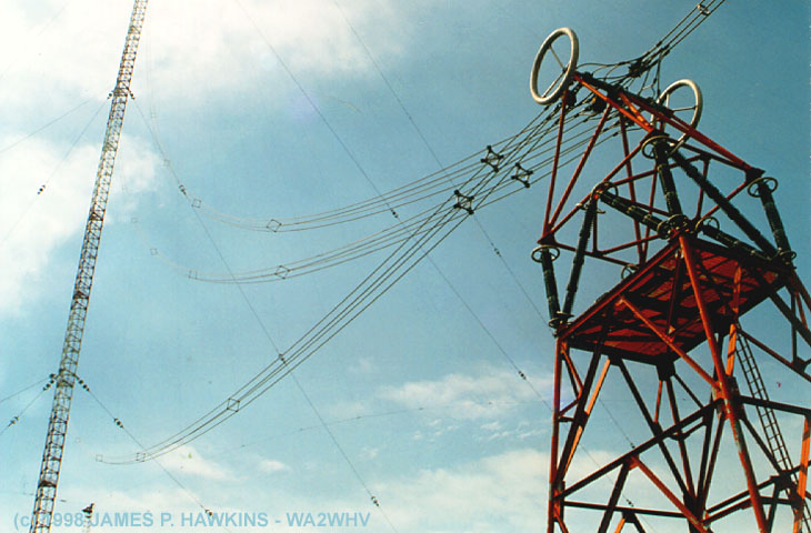
Transmitter building showing
RF lines exiting the roof onto
a support tower where it is split
into three feeds, which connect
to the 1200.The three lines are strung from
the support tower to the 1200'
centertower at points 300, 600
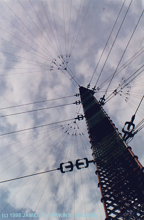
and 900 feet above the ground.Looking up the center tower
of Goliath. Wires radiating from
the top form a capacity top hat to
electrically lengthen the wavelength
of the antenna.
|
|
|
|---|---|
|
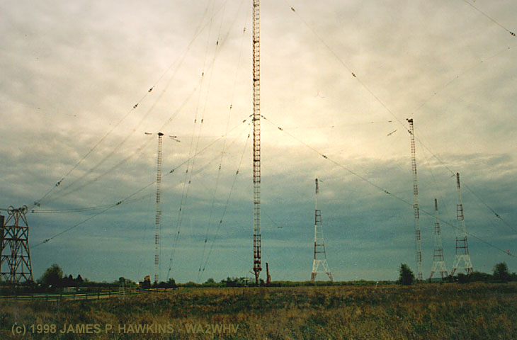
A dreary sky looking picture |
Giant base of the main tower |
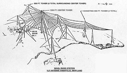
| The central tower is surrounded by six 800' towers which support the capacity top hat. There is actually an elevator inside the main tower which stopped operating in 1995 and has never been repaired. There were other towers called "Eiffel" towers which were built in 1936 and are no longer in use. |
 |
|
Drawing of Goliath Antenna System |
|
|
|---|
|
Tower lights are standard 110-120V lights. You |
If you are fascinated by high voltage objects like the one above
be sure to visit Tesla Science Center
page.
WATER COOLING
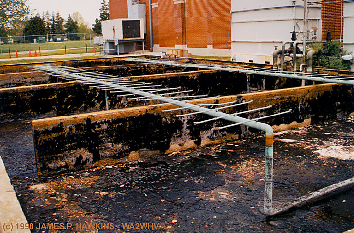 |
| Drained water cooling pond with sprinklers. Water was cooled by spraying it into the air. |
MORE ON LITZ CABLE

Each of these litz cables appeared to be
about 5 to 6" in diameter. They were
composed of smaller cables, each being
composed of yet smaller cable down to
strands almost as fine as steel wool!
| The litz cable, used throughout the NSS antenna system and in the variometers is made in Germany and consists
of over 100,000 insulated copper strands surrounding a hemp core. This made the wire appear electrically longer
in wavelength and increased the conductive surface area. The term "Litz," is derived from the German word "Litzendraht." In a German-English dictionary: Litze is defined as lace, cord, braid; Draht is defined as telegraph, wire. It describes a conductor consisting of a number of separately insulated strands that are twisted or braided together. The litz design equalizes the flux linkages and reactances of the individual strands causing the current to spread uniformly throughout the conductor, because each strand tends to take all possible positions in the cross section of the entire conductor. The A.C. to D.C. resistance ratio then tends to approach unity which makes this design very desirable in high Q circuit applications. Some of the above info was found at the New England Electric Wire Technologies Website. |
|
W W W VVV VVV VVV DE NSS NSS NSS I used to hear this CW sequence some time ago on several shortwave frequencies go on and on for as long as
I could stand to listen. I never talked much about it, but some other friends e-mailed me and mentioned that they
had heard this also. Well, at the time of this writing, I received some information from the late Richard Dowden1,
Emeritus Professor of the University of Otago at Dunedin, New Zealand, who explained it as follows: |
![]()
BACK TO "JIM'S RADIO ROOM" MAIN PAGE
Other VLF Transmitter Pages
Navy Shore Station LF & VLF Transmitters
Radio Station Grimeton.
VLF station transmits with AC generator!
Welcome to the Realm of Natural VLF Radio (0.2 - 11 kHz) Stephen
P. McGreevy, N6NKS
2 thoughts on Potomac Valley Radio Club (PVRC) and the US Naval Academy Radio Club to operate NSS special event
May 13 Brian - W9IND
Robert H. Snyder's RTF, Hawaii site
| Accessed | times since April 22, 1998. |
![]()