Jim Hawkins' Atlantic City
Radio Technical Page


This page is a tour of
WFPG-FM 96.9, WFPG-AM 1450,
WMID-AM 1340, WSAX-FM 99.3
and WJSX-FM 102.3.
The studios are located at Northfield and Venice Park, NJ
and the transmitters are located in the
well suited meadows of Atlantic City.

WFPG-FM Microphone.
Electro Voice RE-20


ACNOWLEDGEMENTS

I would like to thank Tom McNally for taking me for the grand tour of the studios and 3 transmitter sites. Tom has worked in broadcasting as a DJ, Program Director, and engineer for over 25 years and is now:
Chief Engineer of WFPG-FM 96.9, WFPG AM 1450, WKOE 106.3, WPUR 107.3
Contract engineer for WMID, WSAX, WJSX, WJPH
Standby engineer for WTTH, WBNJ, WZBZ, WAYV, WCMC, WZXL, WBSS, WCZT, WWZK, WJNN, WJSE


The long list of station responsibilities for Tom McNally reflects how things have changed for today's broadcast engineer as opposed to the earlier days of radio.

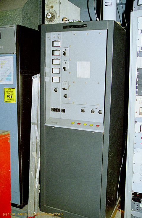
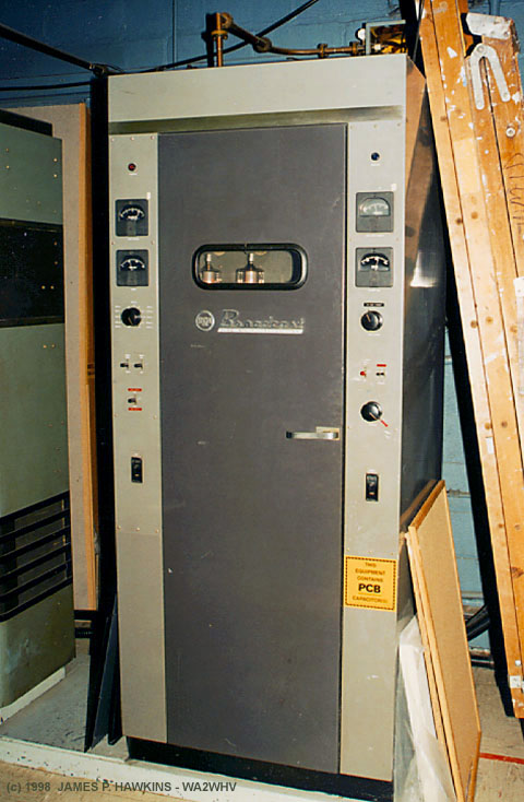
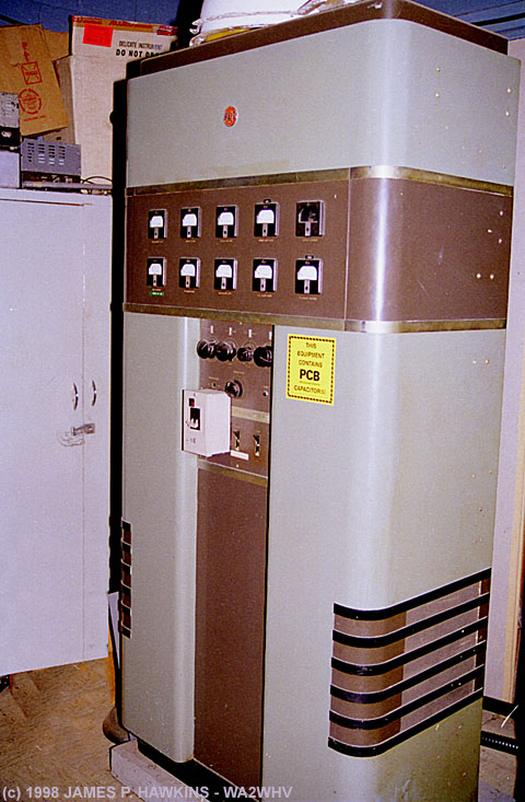
From the early to middle part of the 20th century, many engineers lived at a single transmitter site and 
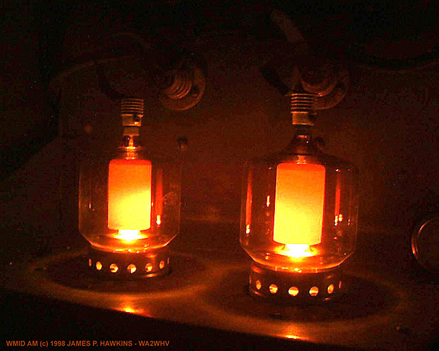
tended to transmitters for one station. When most transmitters used very high voltages and depended solely on one 
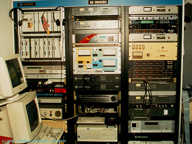
or two tubes for the output, failures were more frequent. As this century has approached its end, most modern transmitters became mostly or all solid state. New AM transmitters use voltages which may range from 50-300 volts in many cases. 
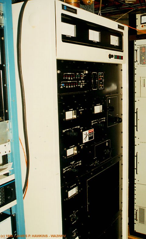
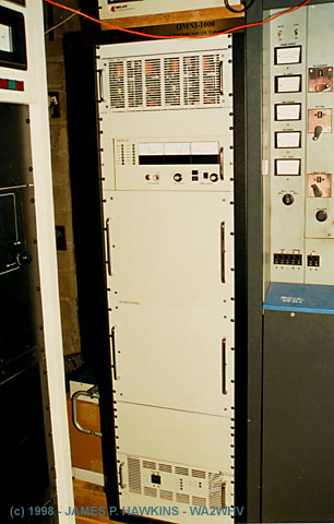
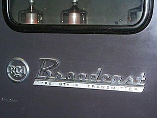
Newer transmitter tubes are designed and constructed with more precision methods using sophisticared CAD (Computer Automated Design) systems and raytrace technology. That, in addition to better engineering and built-in redundancy have drastically reduced the maintenance requirements and increased MTBF (Mean Time Between Failure) for individual station equipment. Single or push-pull tube outputs have been replaced with stacked, lower power modules, the failure of which no longer results in transmitter downtime. As a result, today's broadcast engineer is responsible for more stations and is required to learn new skills rapidly because of the rapid pace of technological change. He 
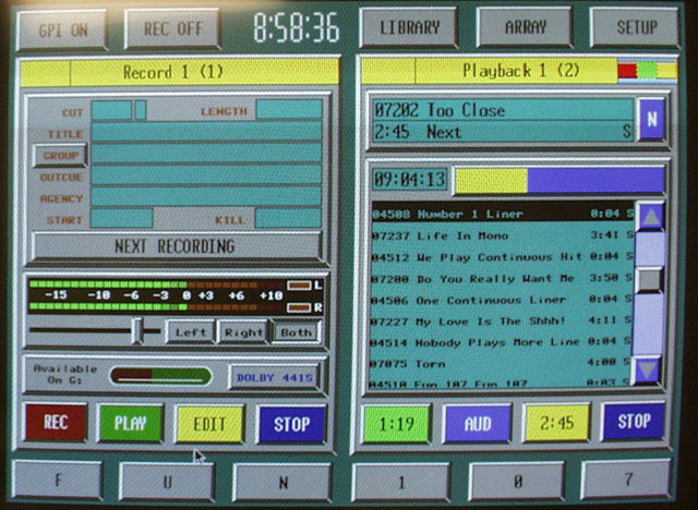
or she must be computer saavy as most new equipment is computer controlled. They also find themselves working as a consultant to other stations. There are still some cases where engineers live on site as is true with Paul Jellison at WLW in Cincinnati. But, Paul is also responsible for all Jacor owned sites in the Cincinnati area. This is becoming true in many other industries. Being in the computer industry, myself, I know that consultants are used on an increasing basis and more time must be spent learning new technologies.

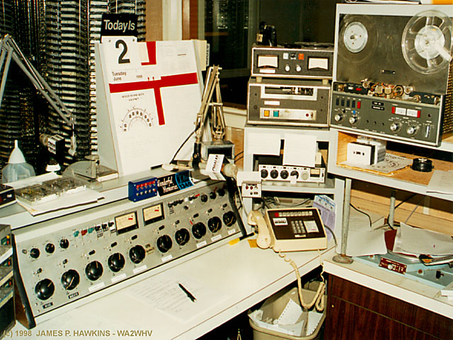
Most books you find on radio broadcasting are about the stars and the talent of radio. However, without the hard and often dangerous work of radio inventors, engineers and technicians, the success of the great stars of radio would not be possible. It is the powerful radio transmitter (the "rig") that screams out the sounds of talent and messages of the sponsors, who pay for the programs with money earned from the listener. The technical staff is responsible for maintaining this equipment. The larger the audience, the more costly it is to lose precious seconds of equipment down-time and when equipment goes down, the technical staff hears about it!

Finally, TV and FM are the last holdout to full solid state transmitters and with 18 months left, the year 2000 may mark the final goodby to the manufacture tube transmitters for standard broadcast (not to mention the beginning of digital television and radio).

---Jim Hawkins


WFPG-FM 96.9 and WFPG-AM 1450
WKOE-FM 106.3
WZZP-FM 107.3


STUDIOS of
WFPG , WKOE , WZZP
(Northfield, NJ)

Studio building located at
950 Tilton Rd.,
Northfield, NJ

One of the many studio
consoles. This one is a
Radio Systems RS-12.


WHERE THE MUSIC IS

Music, commercials and promos
are all stored on computer hard drives
This replaces records, tapes, tape carts
and CDs (although CDs are used to
dub in new material). Audio is stored
in compressedDolby-AC2/MPEG form.

Screenshot of DADpro Digital Audio
Delivery System in operation for
automatic program control. All audio
is stored on the disks shown on the left.


At startup, 500 songs were selected from a catalog and ordered online, shipped to the station in digital form and loaded onto the hard drive on the computer network (Novell is this case.) Thereafter, new songs and libraries are dubbed digitally at 44.1 kHz from CD's at the station ... purchasing a library was a one-time thing. Songs, commercial spots, station promos, etc. can be put together and a variety of transitions between selections can be chosen. Each announcer runs their own copy of this program from the computer network.


CONTROL ROOM

Central control room for all
stations in the building. This
is also CE Tom McNally's
office.


These racks contain processing equipment for the various stations.

  • Studio-Transmitter links
  • Audio processing
  • Compressors
  • Reverb
  • Talk Show Delay (to dump out naughty things callers might say)
  • Master Clock system to synchronize the clocks in all the stations
  • EAS (Emergency Alert System) unit
  • Optimod Stereo generator for WFPG


TRANSMITTERS

WFPG Harris 25KW Model FM25K1 transmitter.
The final is an 8990 (4CX20000)
WFPG OMNI 1 KW AM solid state transmitter
using Pulse Duration Modulation.
Only top two and bottom (power supply)
panels make up the transmitter. The panels
in between are empty space, so the whole
transmitter is quite small. The unit just to
the right is a backup Sintronic model FM3K
FM transmitter. You could hear the audio out
of this unit....
"tsssst tssssst tssssssssst tsst tsst tsst tsst"


ANTENNAS

FM Antennas on top
of AM tower

Bottom of Folded Unipole
AM Antenna.


In this case, a folded unipole is used. In this case, 6 wires run up the outside of the tower antenna. They are fed at the bottom above insulators and all connected together and to the tower at the 900 phase point. In effect, these outer conductors form the outside of a coaxial transmission line. The radiating current of the outside wires and that of the tower cancel. The outside wires plus the rest of the tower above the 900 point electrically form a bottom insulated half wave vertical radiator. The shorting or feed point is adjusted up or down to tune the antenna. The antenna current goes to 0 at the top of the tower. The folded unipole is named so, because it is a modification to a slant, shunt fed antenna with the feed folded parallel to the antenna. It's a clever way to use a grounded tower as a vertical radiator which can also be used to support FM antennas at the top.
REF: 1) Tom McNally, CE of WFPG. 2) NAB Engineering Handbook, 8th edition. 3) Radio Frequency Transmission Systems, Jerry C. Whitaker. 4) LBA Technology, Inc.

Another example of a folded
Unipole with three fold wires.

The antenna on top of this tower is
WMGM-FM 103.7, 50 KW
directional, the folded unipole is for
WOND-AM 1400, 1KW and also for
WGYM-AM 1490, 290 watts.


WMID-AM 1340 Atlantic City
WSAX-FM 99.3 Pleasantville
WJSX-FM 102.3 Cape May


STUDIOS of WMID and WSAX/WJSX
(Venice Park area of Atlantic City)

Older vintage equipment.

WSAX Studio with
Radio Systems RS-18 console.

Cartridge "Carousel" rack and
closup. Automates preloaded
"cart" selection and sequencing"

Racks of individual "cart"
machines and reel-to-reel
tape deck

A "Cart"

Broadcast continuous loop
cartridge. Pop in a song, jingle
commercial or promo. Uses
queuing tone.


TRANSMITTERS

Auxiliary equipment rack with
audio processing, FM
Exciter/modulator.
WSAX 5 KW RCA MODEL BTF-5E
FM transmitter for WSAX 99.3,
Pleasantville, NJ.
It uses a 4CX5000 final tube.
Backup Sintronic Model FM3K transmitter
for WSAX.
WMID RCA BTA-1R 1KW Main AM
Transmitter. This transmitter uses a pair of
4-400s for the modulator and a pair of 4-400s
for the RF final amplifier. On this transmitter,
the "tires are rotated" every 6-12 months, so
to speak. That is, the 4-400 pair in the
modulator is swapped with the pair in the RF
final, since the modulator tubes are driven
harder.
WMID RCA BTA-250L 250W AM Backup
transmitter (vintage - 1947). There are
are two 810s in the final. Automatically
comes on if main transmitter fails.


More on the RCA BTA-1R
("Real Radio Glows in the Dark")

Closup showing transmitter
label and tube window.

4-400A Modulator tubes in
full CCS operation.

BTA-1R Tubes

Oscillator 6AK5
1st RF amplifier 5763
2nd RF amplifier 6146
Final RF amplifier 4-400A(2)
1st AF amplifier 2E26(2)
Modulator 4-400A(2)
Bias rectifier Selenium
Low-voltage rectifier Selenium
High-voltage rectifer 8008(2) - Replaced with
solid state at this station.


ANTENNAS

300' Blaw-Knox tower for
WMID with a 50' additional top
section (36" wide), added
around 1995 for WSAX-FM.
Picture of Austin isolation
transformer (Austin Rings),
"Johnny Balls" for lightning
arrest near one foot of the
Blaw-Knox tower.

Since the tower is energized with RF you have to isolate the tower light circuit from the incoming line. The space between the interlocking rings provides the high high voltage isolation. The bottom ring is the primary with the windings wrapped in a helical fashion around the ring. The secondary is the upper ring with the windings running around the circumference intersecting the 60 HZ alternating magnetic field of the primary, thus, coupling 115 volts to the tower lights. The "Johnny Balls" are set at a gap large enough so that the RF voltage on the tower cannot arc to ground under normal conditions, but lightning will jump the gap, diverting the current away from the transmitter. An unusual variation of the Austin isolation transformer can be seen on my NSS page.

TOP AND BOTTOM

Top of Blaw-Knox tower
showing extension carrying
WSAX-FM antennas.

Foot of Blaw-Knox tower
showing intricate insulator
support assembly on concrete
base.


BACK TO "JIM'S RADIO ROOM" MAIN PAGE


Accessed times since June 6, 1998.

Fine Print:
All images are Copyrighted and are provided for your personal enjoyment. Use of these images for commercial purposes including their distribution on CD-ROM or any other media without my permission is prohibited. Contact: Jim Hawkins