 |
|
RCA BTA-50F Panorama - Click on image and scroll! |
| Thanks to CE John Hovanec for inviting me to the facility and taking some time to give me a tour during the
2001 memorial day weekend. John was Chief Engineer at WKNR from 1990-1994, where he was responsible for most of the new studio and Master Control design and rebuild, including new ground system put in for the antenna system, then again from 1998 to present. Thanks also to my wife Gretchen for some photo suggestions and for asking questions that I did not think of. Thanks also to Scott Fybush for supplying the call letter history information and to Ludwell Sibley for supplying additional information on the 5671 tube. My gratitude goes to former Engineering Manager, Jack Sellmeyer for writing a long e-mail about WGAR, which is featured as an article on this page. |
|
|
RCA BTA-50F Panorama - Click on image and scroll! |
|
|
|
| Look for Real Audios of air blowing through 5671s Singing Modulation Transformer and "singing" coils of phasor unit at the main tower. |
 |
|
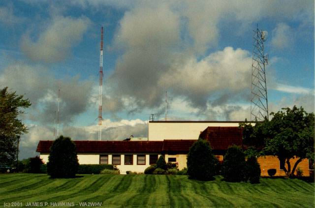
Transmitter and Studio building. |
|
| WGAR(AM) changed its call letters to WKNR(AM) on July 13, 1990, only a couple of years after the WGAR calls
appeared on FM in Cleveland, on 99.5. With this call letter change, the country format was dropped for talk radio. The WKNR call letters were once used by a Detroit station ("Keener"), but dropped long before WGAR made its change. The Detroit station became WNIC(AM). By 11/24/1986 it had changed to WMTG ("Motown Gold"), WDOZ ("Radio Aahs") on 1/3/1995, WYUR ("Your Radio") on 9/22/1997 and, finally, WXDX(AM) (sports) by 12/24/2000. Thanks to Scott Fybush for the call letter information! Scott is a regular column on radio market information online and also a regular columnist for magazines such as Radio World. His website is updated regularly with radio news information. |
 |
 |
 |
|
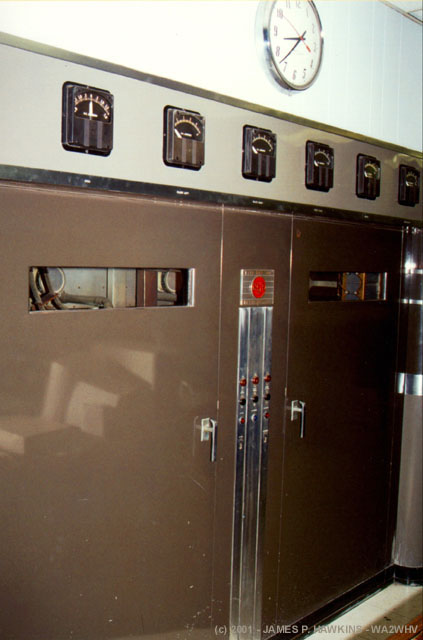
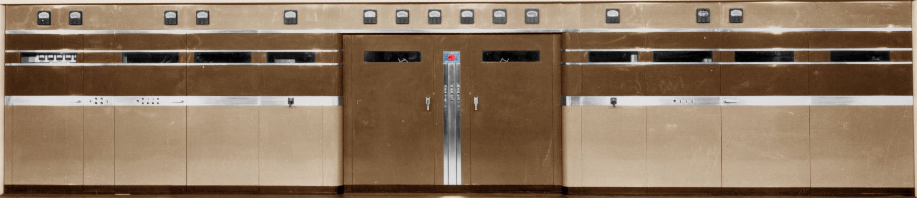
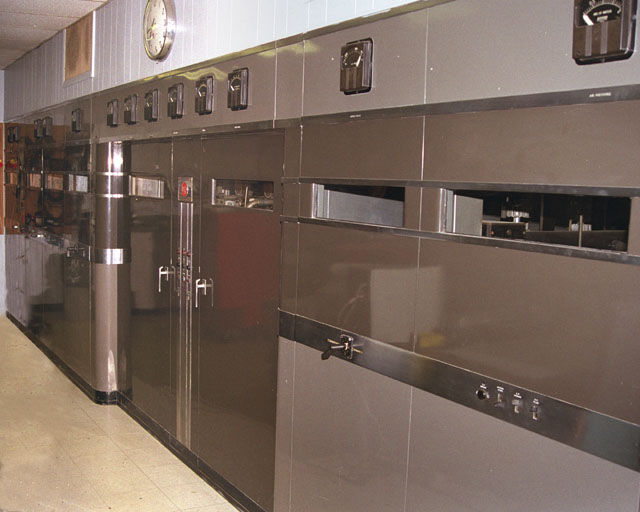
View from Left End |
Trademark Plate |
View from Right End |
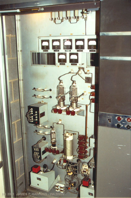
| This transmitter was previously owned by WBAP 820 in Fort Worth, Texas 1972. There were originally two of these
transmitters at the site, but the other one was replaced by a Harris MW-50 transmitter and a row of auxiliary equipment
racks. The remaining BTA-50F is located in a very shallow room, which is a combination workshop and office for
the engineers. Above are views of the transmitter from both ends. The trademark plate is on a vertical strip at
the center of the transmitter. These art deco cabinets were designed by John
Vassos, who worked for RCA for 40 years. The first 50F was sold to WEEP, Pittsburgh. Layout: 1st cubicle - RF drivers 810s driven by 828. The 810s drive an 892-R in back of the inside panel, which ultimately drives the 5671 final amplifier tubes. 2nd cubicle - modulator with three 5671s, one is a spare. 3rd cubicle - RF cabinet with four 5671s, two are spares tank circuit is in the back. 4th cubicle - HV rectifiers. Panel between 3rd and 4th cubicle - a doorway to the back of the transmitter. |
|
|
|
|
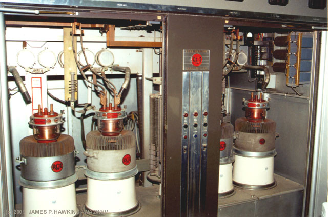
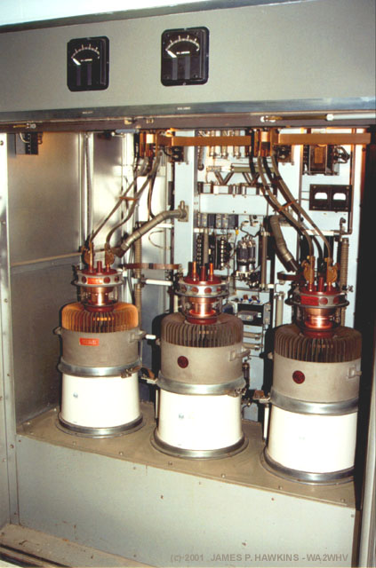
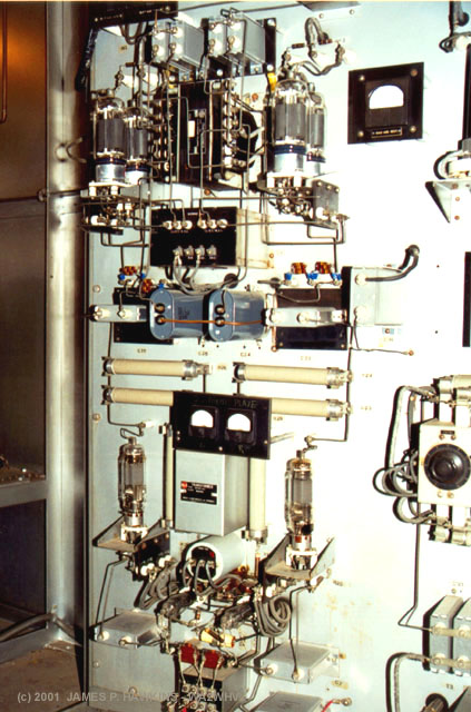
| Center Cabinets contain RF Finals |
Open Cabinet showing 5671 |
RF cabinet from rear |
| The RF amplifier consists of a pair of 5671 air cooled power triodes. There are two extra tubes in place, which can be switched by moving some wiring, allowing bad tubes to be physically replaced later. Each tube is over 200 lb. and requires a special lift designed to remove and replace them. When plate voltage was applied the readings were 10.9 KV at 4.5 Amps. The input power 120kw avg. |
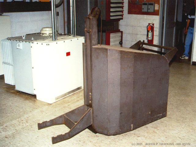 |
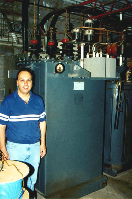
This is the tube transporter for the 5671s, a hydraulic lift, which is hand pumped with the handle on the right after centering the forks underneath the "door handles" on the sides of the 5671s. In the background is the power transformer for the Harris MW-50 main transmitter, which is shown below. |
|
|
An 892-R air cooled triode drives the two 5671s. 892-Rs were very widely used as finals for 5 KW broadcast transmitters. This tube is in a cabinet next to the finals in back of a metal wall. Dividing the front and back of the cabinet. |
|
|
In the front half of the driver cabinet, a pair of 810s drive the 892-R. An 828 drive the 810s from below. |
|
|
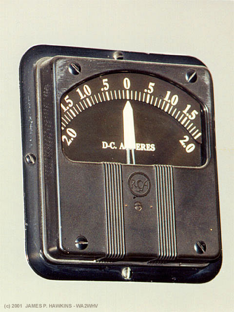
Big RCA panel meter. |
|
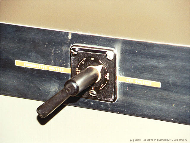
Control switch handle.. |
|
|
Modulator cabinet. Two outer 5671s are connected. Center one is hot spare. The back door has the entire audio drive circuitry. |
 |
The back door of the modulator cabinet holds the entire audio drive to the modulator. The input is 600 ohms 10dBm to a pair of 6C6s. The following stage is a pair of 828s, which drive four 813s in a parallel push-pull circuit. The 813s drive the 5671s. The door has a set of contacts, which, when closed, connect the circuitry on the door to the modulator output tubes circuitry in the cabinet. The 813s replaced a former design with 828s. |
| Sound of forced air through 5671 as cabinet is opened. |
|
|
CE John Hovanec standing next to the modulation transformer, which is between 5 and 6 ft high. It weighs 6400 pounds including 190 gallons of 10-C oil weighing 1400 pounds. |
|
|
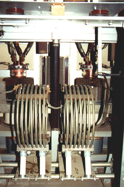
Modulation choke in the center and right of the modulation transformer. It weighs 3600 pounds including 135 gallons of 10-C oil weighing 1000 pounds. The plate supply choke is to the right. |
| Modulation transformer "singing" |
|
|
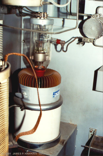
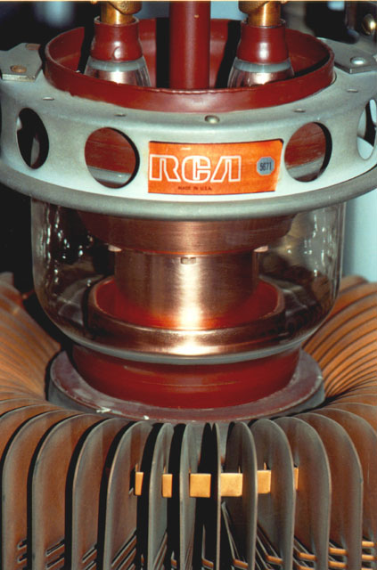
5671 sitting in cooling chimney. Note: 813 for size comparison. |
|
|
Close-up of lit tube in lit room. (Notice perforations in each cooling fin - bottom right) |
|
|
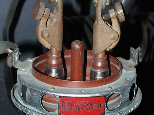
Shows two filament connection clamps on top. Rim is the grid connection. |
|
|
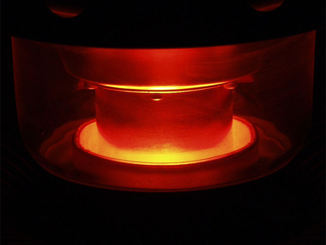
Close-up of lit 5671 in the dark. Filament is 11 V. at 285 A. That's 3135 Watts! |
| Cathode (filament) | 11 V 285 A. |
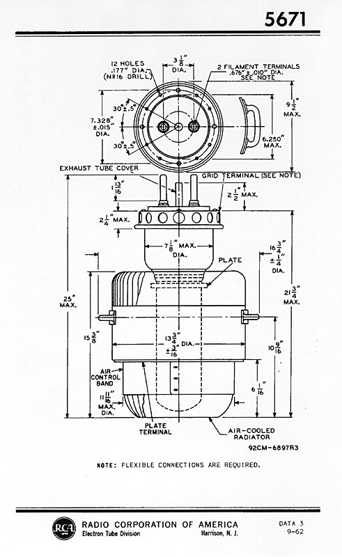
| Dimensions | 25"L X 8.5"D |
| Amplification Factor | 40 |
|
Class of |
Max. Freq. |
Max. Plate Ratings |
||
|
Volts |
DC Input Watts |
Dissipation Watts |
||
| B |
------- |
15000 |
90000 |
25000 |
| C-P |
10 |
12500 |
55000 |
17000 |
| C-T |
10 |
15000 |
100000 |
25000 |
|
Class of |
Max. Freq. |
Typical Operating Conditions |
||||||
|
Plate Volts |
Grid Volts |
Peak AF |
Plate |
Plate-to- |
Approx. |
Approx. |
||
| B | ------- |
15000 |
-320 |
1600 |
10z |
3320 |
600 |
100000 |
| C-P | 10 |
12500 |
-1500 |
------- |
4 |
------- |
1960 |
40000 |
| C-T | 10 |
15000 |
-1500 |
------- |
6 |
------- |
2040 |
70000 |
|
KEY |
|
| B C-P C-T Superscript z |
Class B Push-Pull AF Modulator Service Class C Plate-Modulated Telephone Service Class C Telegraph Service Maximum Signal Value |
5671 Physical Outline
|
|
|
Other notes:
|
|
|
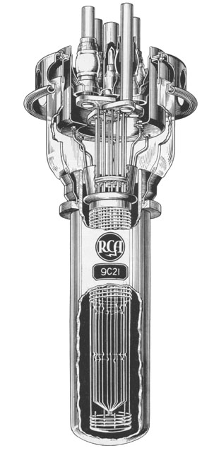
9C21 Image from: The Encyclopedia Americana Vol. 23 1957 Ed. |
|
|
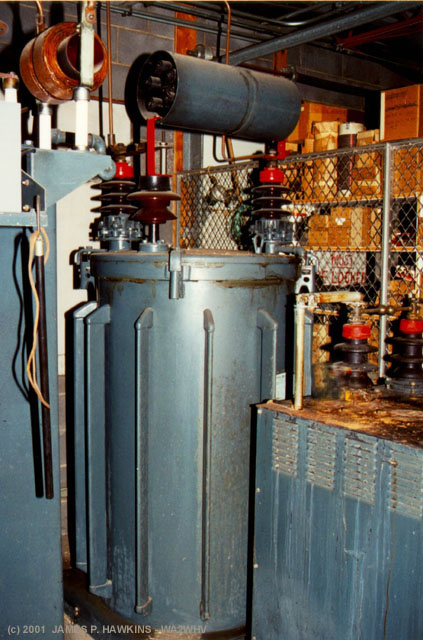
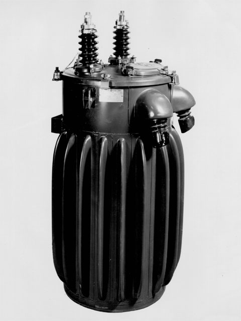
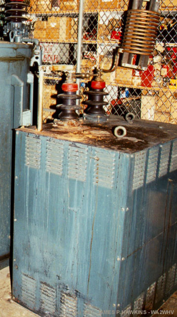
Old photo of HV power transformer. There are three of these outside of the building, one for each of 3 phases. Photo: Courtesy John Hovanec |
|
|
Original 857B mercury vapor rectifier configuration. Photo: Courtesy John Hovanec |
|
|
Solid state rectifier stacks replace mercury vapor tubes. |
|
|
Fusible linked scheme on the power supply capacitor bank. If there's too much current flow, the wire link melts, causing the spring loaded shorting bar across the capacitor to discharge remaining charge. |
|
|
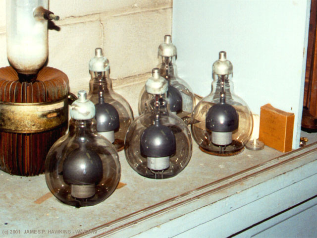
Mercury vapor tubes still in the stock room. Notice the "sick" looking 892-R at the left. |
|
|
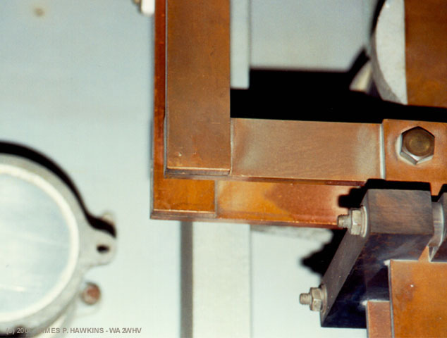
Plate supply choke in front of the modulation reactor. |
|
|
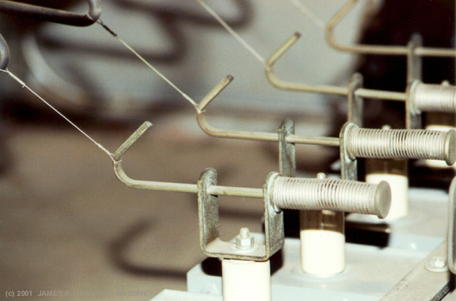
This heavy copper bar carries filament current to all of the 5671s. |
|
|
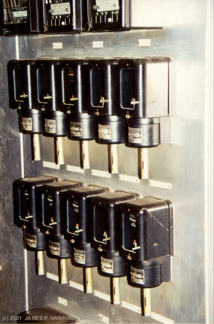
Overcurrent relays. |
|
|
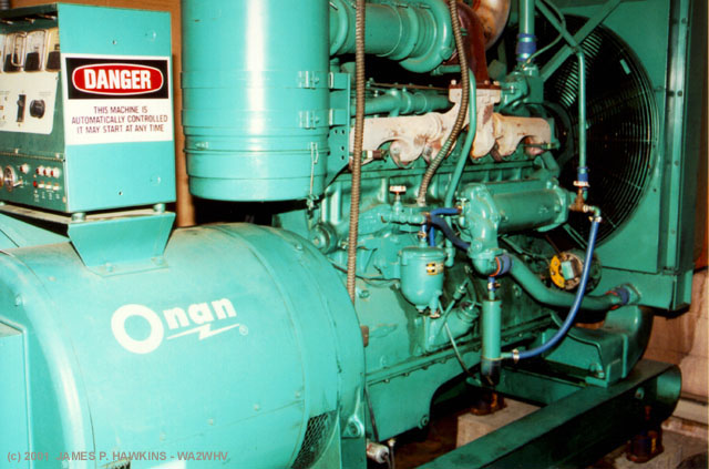
| 250KW Emergency Generator |
|
|
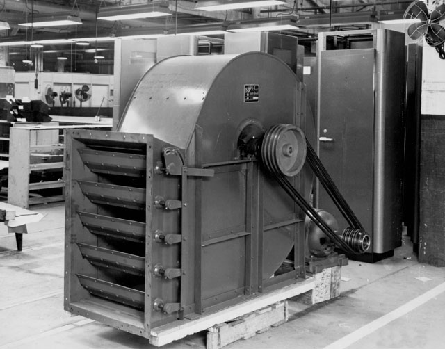
Huge blower, powered by a 7 1/2 HP motor. It's about 6' high. |
|
|
RCA photo of blower before it was installed. Courtesy: John Hovanec |
 |
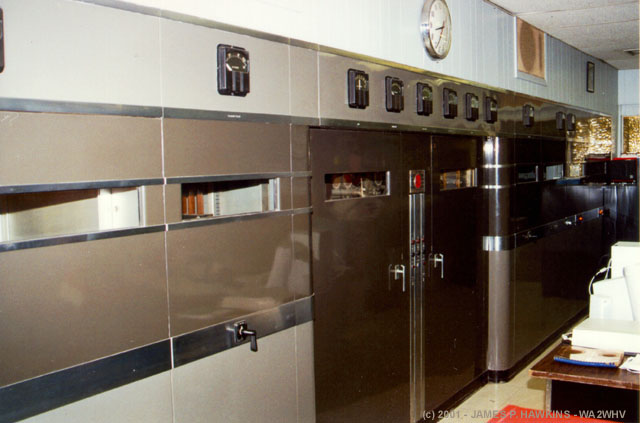
Harris MW-50 Pulse Width Modulated 50KW transmitter. Audio processing equip. in foreground. |
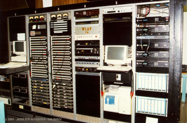 |
Auxiliary equipment. Patch panels and distribution amps. |
The Harris MW-50 transmitter and the auxiliary equipment racks in the place where the second RCA transmitter
used to be.
|
|
Master control boards for audio and transmitter monitoring. The studio behind the window was on-the-air at the moment of this photo. |
|
|
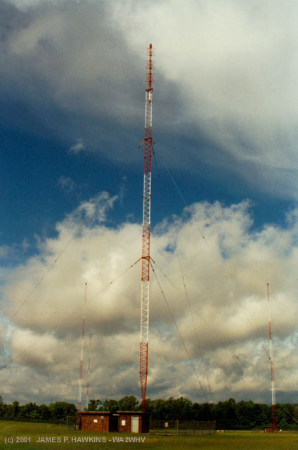
There are 5 towers in the DA of WKNR. The main tower has VHF "Bat-Wings" at the top, which are not in use. |
| Audio sound at the phasor unit at the bottom of the main tower. The coils demodulate some of the audio. The coils are a mechanical analogy to a capacitor (even though they are electrical inductors), which expand and contract with the intensity of the RF signal, but not physically to the RF, itself, causing a mechanical demodulation. |
| The towers are manufactured by Truscan. They are 200 feet high, with 4 of the 5 self-supporting, the fifth is guyed. The Batwing antenna elements are actually an old RCA FM, from when WGAR 99.5 broadcast from this site until the 60's. |
|
|
|
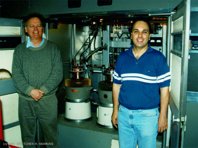
I'm on the left with John Hovanec |
| The original modulator and PA tubes were 9C22'2 which had pure tungsten filaments, hence, an enormous appetite
for power. The original filament supply occupied the entire cabinet located between the modulator cabinet and the RF PA cabinet. Each tube (of the four active tubes) required three separate filament transformers, the secondaries of which were connected in parallel. A separate reactor fed the primary of each transformer. The reactors served both to limit the inrush current to the filament & to balance the load on the three transformers. The original 50F at WGAR (later sold to WEEP, Pittsburgh) was converted to 5671's in about 1948 or 1949 after about a year of operation. The 9C22, in addition to its appetite for power, had significant hum problems due to the filament construction and the enormous current. This problem was dealt with, to a degree, by addition of a "Hum Frequency Feedback Amplifier" in series with the input audio. This device was fed by an RF sample extracted from the output line which was then detected, filtered & added out of phase. The amplifier was not required when the 5671's were installed due to better balance of the filament structure. The 5671 was not developed until the late 1940's; the tube did not exist during the war.....It was developed specifically for high power AM service and had an upper frequency limit of a couple of megacycles, due mainly to lead inductance. It may have been used in induction heating applications, but it was intended primarily for AM Broadcast applications. The WGAR rig was the first application for the tube and the RF PA was converted first, followed a year or so later by the modulators. The radio, as delivered, used four 828's in the audio driver stage. It was a push-pull parallel cathode follower. The stage was not transformer coupled. The only transformers in the audio system are the input to the 6C6's and the modulation transformer. There is a multiple winding reactor between the driver stage & the modulator stage, but it is not a transformer. It's function is to keep the screen & suppressor grids at the same relative potential relative to the cathode as the cathode swings through the full drive voltage range to the 5671's. Due to relatively short life, the 828 audio drivers were replaced with 813's which had a little more filament horsepower. This took place at the same time as the modulators were changed. These two changes resulted in a new model number - BTA-50F1. The F1 versions had a much smaller filament transformer housing between the modulator and RF PA cabinets. The Richards group at the time (immediate postwar) owned WJR, Detroit, WGAR, Cleveland & KMPC, Los Angeles. The Cleveland & Los Angeles transmitters were ordered at the same time with Los Angeles transmitter delivered about a year after the Cleveland transmitter. WJR was using a pre-war Western Electric transmitter and continued to use it until the 1970's. An RCA 5D, 5 KW transmitter was installed in the wall opposite the FM Transmitter and three terminal racks which were installed in the left wall of the transmitter hall. The 5D had begun its life on 1450 KC from a site on Harvard Avenue east of downtown Cleveland in the mid 1930's. It was relocated overnight to the Broadview Heights site during World War II, in mid 1942. A construction permit had been granted for the move to 1220 KC in August or September, 1941, and planning was underway to construct the plant when the Japanese came to visit. The CP was suspended in early January due to the war. After a plea from the Richards group, the FCC agreed to allow the frequency change due to the unusual manner in which the frequency became available for U.S. use. Under NARBA, the channel was reserved to Mexico as a Class 1 clear channel and was not available for duplication in the US at night. A two element directional antenna was constructed on the present site using a pair of 400 foot guyed towers. The east tower which contains the turnstile antenna was one of the elements of this array. It, like the original five tower array, was fed with open wire line from the transmitter building. The transmitter was located in an old farmhouse located south of the present building. One of the original towers was cut down, the other shortened to 200 feet including the pole for FM turnstile and four additional self supporting towers were constructed in 1946 to accommodate the increase to fifty kilowatts. The original antenna system used a rung of 6 wire/230 ohm line from the rear of the 50F to the large block building adjacent to the tower near the center of the array. From this location, identical open wire lines were run to the four towers which form the parallelogram. The coupler for the center tower was located inside the building, adjacent to the phasing cabinet. All of this was replaced in 1972 when the 50 ohm coaxial system was installed. A new building was constructed near the east tower to house the phasing and monitoring equipment at that time and the old open wire line and supporting poles were cut down and removed. The plant sits on about 52 acres which, when properly manicured, looks very nice. The 50F transmitter room featured on this page was added in the fall of 1971 to accommodate the 50F from Grapevine, Texas, the location of the original 570/800/820 KC shared site for WFAA, Dallas & WBAP, Fort Worth. This site was condemned by the Dallas/Ft. Worth Airport board in the late 1960's and was vacated in 1971. The transmitter was sold by Airport Board, not WBAP. The price was $7500 for the entire 50 KW plant. The station had a large quantity of spare parts and WGAR had none. It cost another $7000 to transport the equipment 1200 miles and 400 KC north! The building addition cost about $13000. So, for about $27,500 we had a full power identical alternate main transmitter. As far as I know, we were the only commercial station in the country with 66 feet of transmitter! The tube transporter is a hydraulic lift which is hand pumped with the handle on the right after centering the forks underneath the "door handles" on the sides of the 5671's... The 9C22's had more cooling fins than the 5671's & weighed about 350 pounds. Some of the early 5671's had the same fin structure, but the later ones used fewer fins and weighed about 225 pounds. The tube life was fantastic. Lifetimes on the order of 80,000 to more than 100,000 hours were common. When I arrived at WGAR, no new tubes had been purchased since the early 1950's. I purchased two new ones from RCA and had a pair rebuilt by a company in Massachusetts. The tube was retrofitted into most of the existing high level 50's of the era such as the Westinghouse 50 HG, the GE BT-25 and some others. The Westinghouse 50HG-2, which came out in 1949, used the tube in its original design - 8 of them, one spare for each tube complete with filament transformer. This was done to minimize lost air time if a fault developed, while carrying programming. Standby transmitters, particularly full power standby's at the 50 KW level, were not common in those days. Some other interesting facts from the GE Nameplate for modulation transformer: 6400 pounds including 190 gallons of 10-C oil weighing 1400 pounds; the modulation reactor weighs 3600 pounds including 135 gallons of 10-C oil weighing 1000 pounds. There were two blowers coupled through a plenum and damper arrangement in the original configuration. I chose to install only one on the #2 transmitter since we had a spare transmitter. The original 50F had two blowers installed in the basement at the north end of the building. It was fed by a large, well filtered, air shaft which drew air from the west side of the building. The blowers had separate contactors & could be transferred hot if a problem developed & was recognized by the operator before one of them shut down. The DC Power supply is rated at 150 KVA. This supplies the DC power to the RF PA, the Modulator and the RF IPA, which, itself, draws about six kilowatts. The rating is 55 KW; It is capable of about 60 kilowatts at carrier as designed. The east tower may appear to be taller than the others; I believe it's base is about five feet above the ground level. The electrical height of all five towers is 200 feet. It is probably about 209 feet overall versus about 204 feet for the self supporters including base piers and beacons. --Jack Sellmeyer was the Engineering Manager at WGAR in the early 1970's and was responsible for the two additions to the 1947 transmitter building (studio & the now existing RCA 50F). Edited by Jim Hawkins for this page. |
| Accessed | times since June 11, 2001. |
All images are Copyrighted and are provided for your personal enjoyment. Use of these images
for commercial purposes including their distribution on CD-ROM or any other media without my permission is prohibited.
Contact: Jim Hawkins