WOWO-AM 1190 Transmitter Tour
Fort Wayne, Indiana
9/19/2005

(Jim Hawkins' Radio and Broadcast Technology Page)

IT'S REALLY ABOUT "GEORGE"

Westinghouse 50HG-2 Transmitter


This Page features the Westinghouse Model 50HG-2 transmitter of WOWO, installed in 1953. It is no longer in regular use, but is still fully operational. The transmitter is actually a 100KW transmitter running at half power. The modulator and RF output, each consist of four, air cooled 5671 tubes. It can also be seen on my WNEW-AM and WQXR-AM pages.

For more on the history of WOWO, please visit "The History of WOWO" by Randy Meyer.

This page is not affiliated with WOWO. Please go to the OFFICIAL WOWO WEB SITE for questions about programming, operation and other WOWO business.

My thanks go to Jack Didier, Director of Engineering for Federated Media for the station tour and his wonderful hospitality!


TRANSMITTER FACILITY FROM GROUND AND ABOVE

Three tower array

Transmitter Building


Transmitter Building in 1961
before addition.

Scanned from QSL


Supplied by John Aegerter
WA9GAR

WOWO Google Sat Map
(Click for large)


TRANSMITTER CUBICLE LAYOUT OVERVIEW

50HG-2 Transmitter
Doors open


Transmitter Cubicle Arrangement

Left Final
Two 5671
(One used)
Output tank circuit
and Matching
Right Final
Two 5671
(One used)

Exciter Cubicle:
Drivers for RF
and Modulator
Audio
Modulator
Four 5671
(Two used)
Control unit with
protective circuits.

Note: This cabinet arrangement is flexible and I have observed somewhat different layouts in photos for other stations which used this transmitter.


MODULATOR


Modulator description from WOWO Transmitting Plant Manual 3/13/64


The audio frequency system of the transmitter consist of the following push pull stages:

A. First audio, two 807s. C. Third audio, two WL 5736
B. Second audio, two 813s. D. Modulator, two WL 5671

The first class A audio stage contains a line to grid transformer, which can be connected for either a 600 or 150 ohm line. This stage has individual cathode bias for each tube. The plate circuit is resistance coupled to the following stage.

The second stage (class A) has individual bias adjustment for both tubes and is resistance coupled to the following stage.

The driver class AB stage is a cathode follower, with an individual bias supply for each tube. This stage is directly coupled to the grids of the modulator tubes.


The class B high level modulator stage employs two WL 5671 tubes in push pull. These tubes have thoriated* tungsten filaments. Individual bias supplies, adjustable, and with separate indicating instruments, are used. A spare tube socket and filament transformer are provided for each of the modulator tubes, with switches used for quick replacement.

The audio power is fed to the final RF Amplifier across a modulation reactor, making it unnecessary to pass the plate current for this stage through the modulation transformer. An equalizer circuit stabilizes the modulator load impedance to permit the application of inverse voltage feedback.

*Thoriated - Thorium, a radioactive element, is added to the tungsten, which allows it to operate at higher temperatures.


Modulation Transformer, which is about
6' high.
The modulation reactor is behind the
transformer.


RF AMPLIFIER and DRIVER CUBICLES

Drivers to 5671 final
and modulator

Drivers with door
open. Left pair is
audio. Right pair is
RF.

5736 Driver Tubes
Driven by 813s then
by 807s in the back.
One of two RF output cubicles.
Close-up of 5671 with RF choke
on the right towards the back.
View from rear.

RF Amplifier description from WOWO Transmitting Plant Manual 3/12/64


The radio frequency system of the transmitter consist of the following stages:

A. A WL 802 crystal oscillator with OD3/150 regulator tube.
B. A WL 807 buffer amplifier.
C. The first amplifier, two 813 tubes in parallel.
D. The second or driver amplifier - two WL 5736 tubes in parallel.
E. The final amplifier, two WL 5671 tubes in push pull.

The type FA crystal oscillator is an individual plug-in unit containing the TMV 129B crystal and heater assembly, the oscillator and regulator tubes, and the associated circuitry. Frequency stability is maintained by the use of a highly stable quartz crystal in an electron coupled circuit. The crystal is kept at a constant temperature in an automatic oven. Approximately 15 watts of 115Vac single phase power is required for operation of the oven. To further ensure stability, a voltage regulator tube is used in the screen supply.

Two complete crystal oscillators are included with the transmitter. A relay, operated by a switch on the front panel of the Exciter cubicle, allows transfer from one unit to another. The unit not in use is constantly in readiness with crystal heater and filaments energized.

The Buffer stage uses a lightly loaded 807 tube as a class C amplifier. The grid circuit is untuned, and no neutralization is required. Cathode bias is provided to protect the tube in event of excitation failure.

The first RF amplifier consists of two 813 tubes in parallel as a class C amplifier. The grid circuit is untuned and is capacitively coupled to the tuned plate circuit of the buffer stage. The plate circuit is tuned by a motor driven capacitor. No neutralization is required. Cathode bias protects the tubes in case of excitation failure. A loop coupled to the plate inductor is provided for feeding energy to a frequency monitor.

The second or driver amplifier uses two parallel WL 5736 tubes as a class C amplifier. The grid circuit is connected to a tap on the shunt fed plate tank of the preceding stage. This tap can be adjusted to provide the proper grid drive. Neutralization is accomplished by a variable vacuum capacitor connected between the plates of the 5736 tubes and the plate inductor of the preceding stage. A motor driven variable gas capacitor is used in the tank circuit. Fixed bias is supplied by an individual power supply.

The final amplifier is a class C stage employing two 5671 tubes in push-pull. These tubes have a thoriated tungsten filaments. The grid tank circuit is inductively coupled to the plate tank of the driver stage. The coupling inductor in on ths same coil form as the plate inductor of the driver stage and has a motor driven variable tap for coupling adjustments. An individual bias supply is used for each half of the push-pull amplifier. A motor driven variable gas capacitor is used in each grid circuit. The plate tank circuit of the power amplifier is shunt fed in order that the two motor driven gas capacitors may be mounted on ground. Inductive neutralization is used. The output coupling coil is mounted inside the final tank inductor and has a motor driven variable tap at ground potential. A Faraday shield is used between the final tank inductor and the output coupling coil for suppression of harmonics. A TC ammeter is in series with the output lead. This instrument is mounted behind a glass window in the CPA unit and may be shunted out of circuit by a switch on the lower front panel. A Rectifier type meter is provided for remote indication of the output current. A spare tube socket and filament transformer are provided for each of the operating tubes in the final amplifier, with switches provided for quick switching. RF energy for a modulation monitor may be obtained from the PA tank by tapping on the tank coil end ring at a suitable point.

*Thoriated - Thorium, a radioactive element, is added to the tungsten, which allows it to operate at higher temperatures.


Conductive Lever connector
swings between one final or
the other for quick tube change.

If the transmitter were operating
at full 100KW, both tubes would
be used in each RF output
cabinet.

Shows heavy conductors connected
to cathode filaments 11 Volts @
285 Amperes.
More about the 5671 tube


TANK CIRCUIT AND MATCHING UNIT

Front panels Rear View
Showing matching
and tuning capacitors


RF Matching network circuits
above the tank coil.
Output tank coil


MAIN CONTROL AND FAULT DETECTION CABINET

Front view

Rear view

Overload and interlock
indicator lights

Transmitter controls.


OTHER VIEWS


Backside doors of 50HG
Peering through blue
leaded glass of multiple
open front doors.


COOLING

This enormous Squirrel cage blower
stands about 9' high and is rotated
by a 7.5 HP electric motor.
Looking into the interior of the blower.

The blower pumps air into ducts running under the floor. The ducts run underneath the cabinets directing air up through the porcelain chimney's, which the tubes sit on to cool the tubes. The heated air continues out of the top of the cabinets and into duct work in the ceiling, which was used to heat the transmitter facility.

The modern Harris DX-50 transmitter, shown at the bottom of the page, is very efficient and hardly put out enough heat to even warm your hand.


POWER

AC voltage regulator which works on the principle
of motor driven variable coupling.

Behind the voltage regulator is the plate supply
transformer.
175KW Emergency Generator


MAIN TRANSMITTER ROOM

Harris DX-50 Main
Digital Modulation Transmitter (Right)

Harris MW50A Standby/Backup
PWM Transmitter (Blue)
Behind Main DX-50 and MW-50

Plate Transformer for MW-50
in Left Foreground
Auxiliary Equipment Racks
(Audio Processing incoming links, etc.)

Phasing Unit (Brown) on Far Wall
Inside Phasing Unit

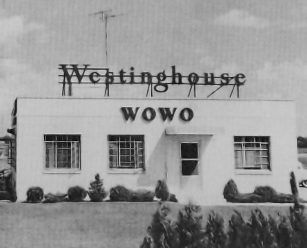
A brief comparison of WOWO transmitters and their technology.


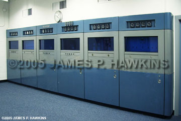
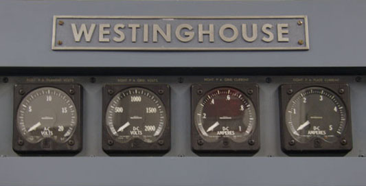
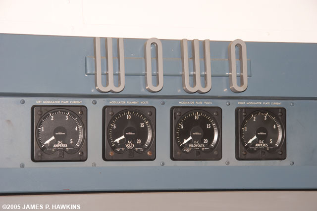
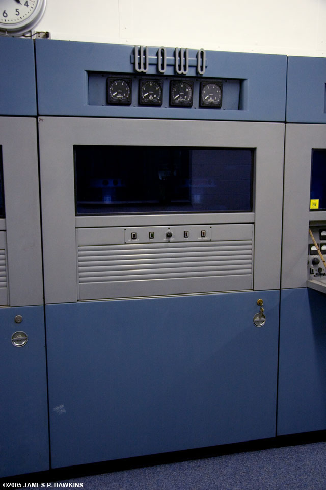
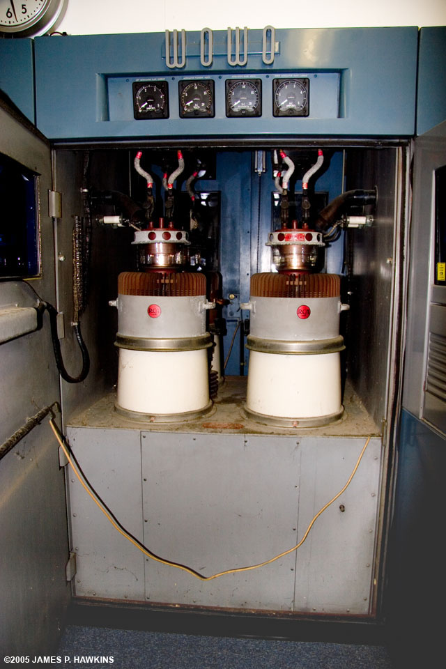
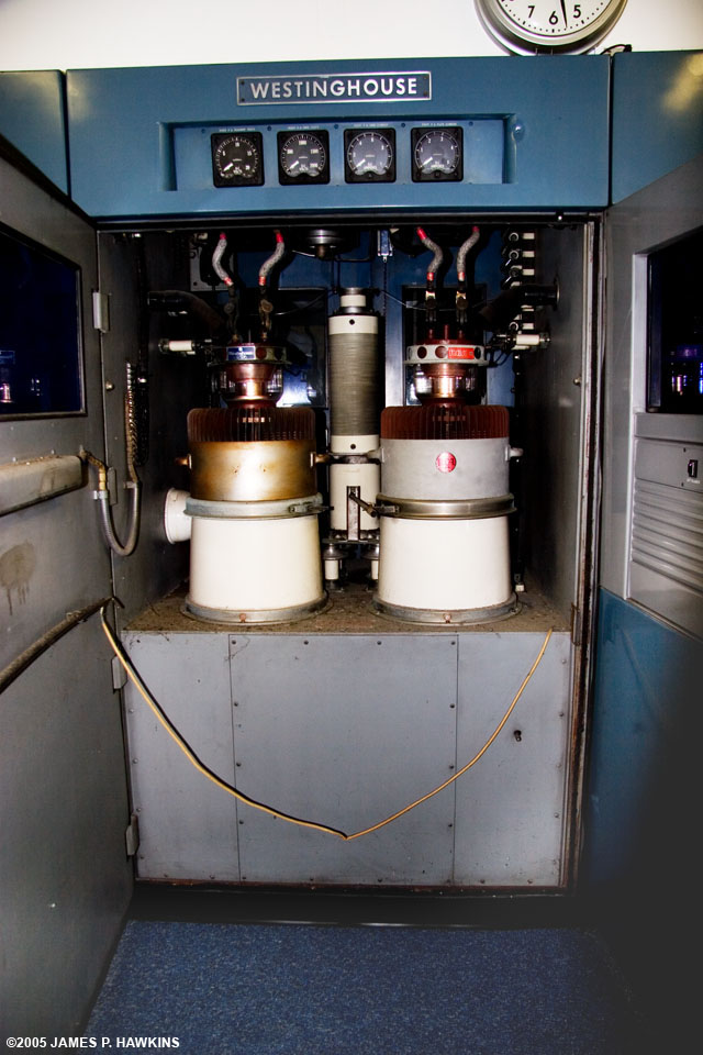
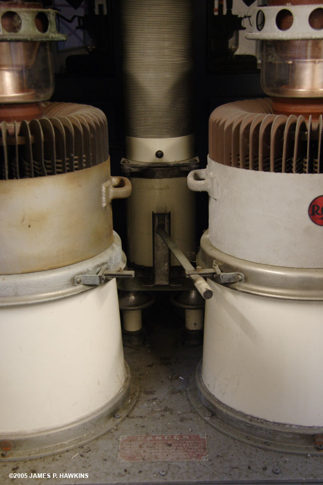
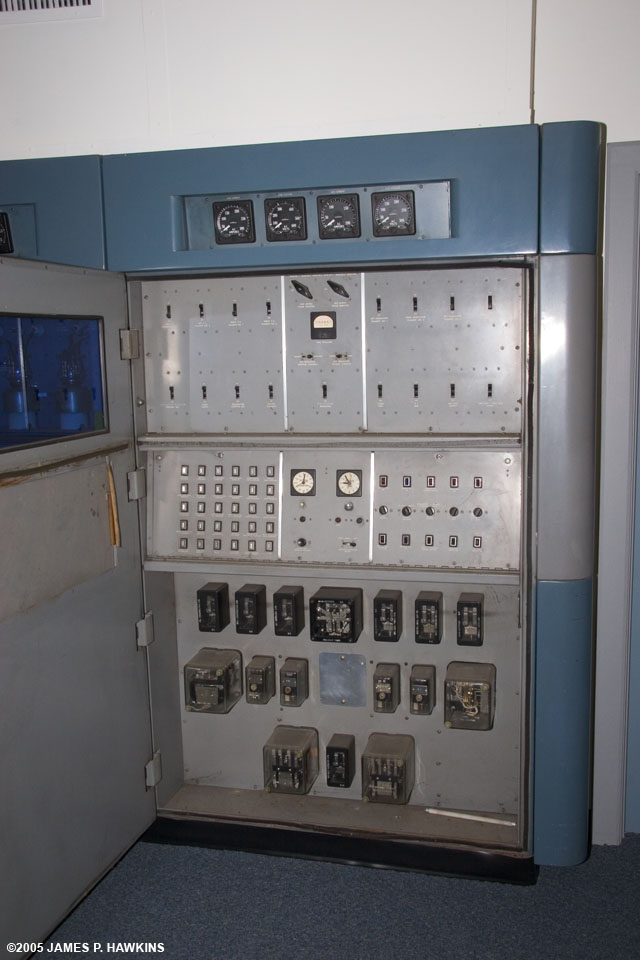
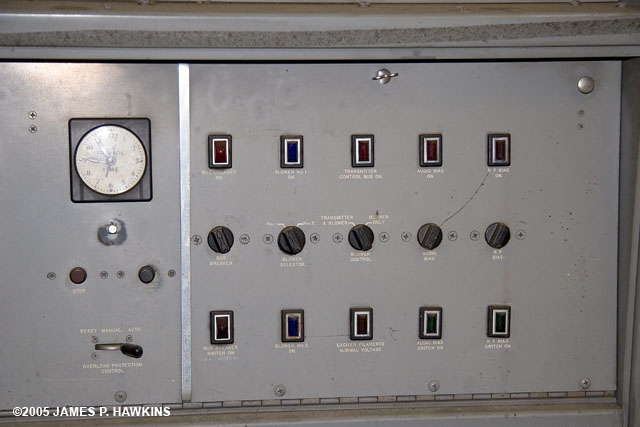
The Westinghouse 50HG transmitter is a high level plate modulated transmitter. Essentially, the modulator is a high powered (25,000 Watts), audio amplifier which adds an audio variation to the plate supply voltage for the RF final, modulating the amplitude of the RF carrier. This requires huge, lossy transformers and tubes operated in active (somewhere between cutoff and saturation) states. In this region of operation, you have a voltage across the tubes and an in-phase current passing through them, which results in further power losses in the form of heat. 
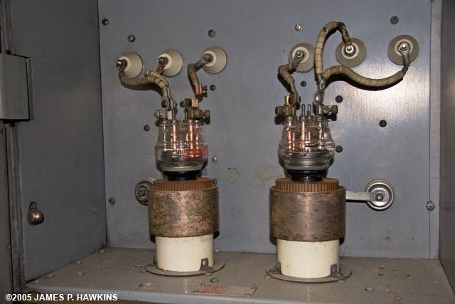
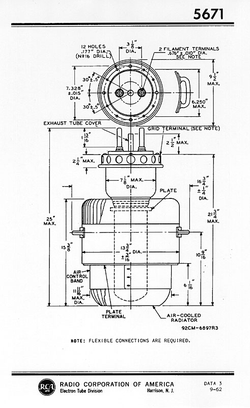
The filaments in the finals and modulator tubes, each require 11V at 285 A = 3135 watts of power. For all four 5671s which must be in operation that's 4 * 3135 = 12,540 Watts just to light the tubes.
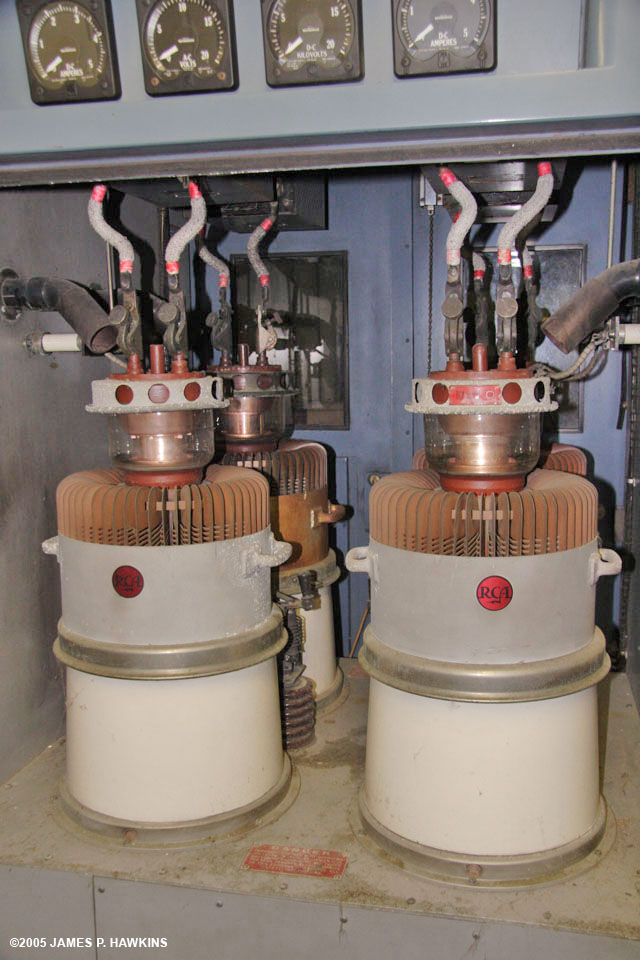
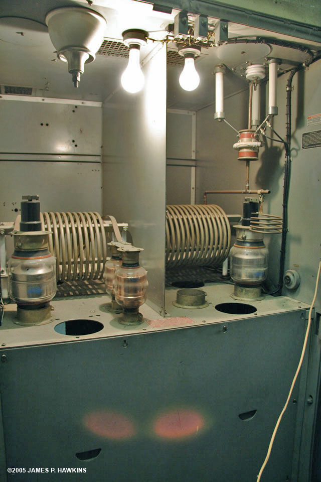
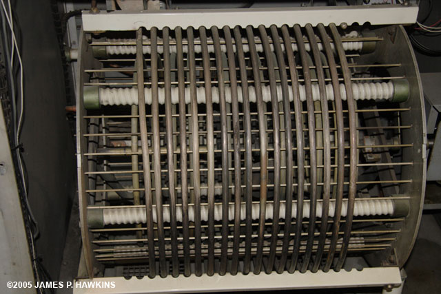
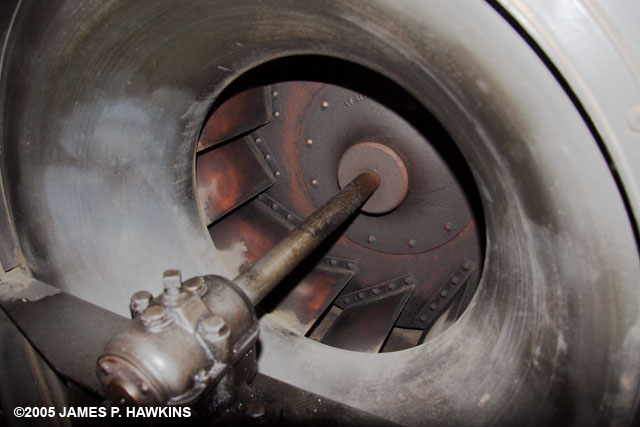
In a class C, RF amplifier, each tube in a push-pull arrangement alternately "kick" energy into the tank circuit from one end to the other. The actual energy pulses from each tube are full of harmonics as the current waveform is very non-sinusoidal. The tank circuit acts like a pendulum, swinging back and forth in a near sinusoidal fashion. It is a combination of inductive and capacitive reactances, alternating the current flow at a the resonant frequency of the combination. In this case the two components are in parallel, forming an anti-resonant circuit, which shorts out (filters) frequencies, which are not at the resonant frequency. (Try making a clock pendulum or playground swing move at a rate which is not at it's natural or resonant frequency.) In this case the energy is transferred or magnetically coupled via a secondary coil "link coupling." All transmitters, modern and old, use the same principles of resonance, to transfer a radio frequency, which centers on the dial position of the radio station.

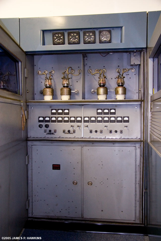
The Harris MW-50 takes a step to reduce the losses by operating the modulator tube(s) at either saturation (maximum current at nearly zero volts) or cutoff (maximum voltage at nearly zero current). Any way you cut it, with ohms law E*I = W, either E or I is nearly zero, yielding a low amount of power loss in the modulation tube. How does this translate to audio? When unmodulated, the modulation tube is generating a square-wave at, say, 70 Khz. With no modulation, the time duration of the "on" portion is equal to the time duration of the "off" portion of the waveform, yielding an unvarying "middle" average. The 70 Khz is filtered out in coupling to the final amplifier. When modulated, the square wave duty cycle is varying in accordance to the audio. At maximum peaks, the square wave has wide, on-cycles and and minimum peaks, the tube has wide, off cycles. The varying duty cycle creates an AVERAGE voltage and current, which corresponds to the audio. It is coupled through a 70 Khz low pass filter to the the RF finals. This is much like a modern light dimmer, which simply chops the power at either longer or shorter intervals. The light bulb, itself has a thermal time constant (it cannot instantly cool or heat), which filters out the chopped part. This type of modulation is called PWM or Pulse Width Modulation.

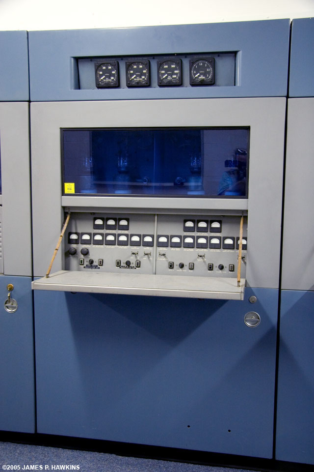
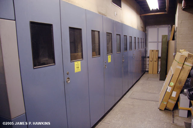
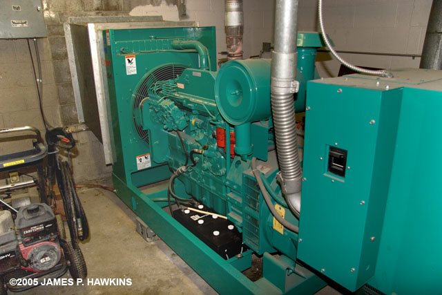
The Harris DX-50 takes a whole different approach, but extends the idea of operating devices in either saturated or cut-off states. This method, invented by the late Hilmer I. Swanson 1932-2005, completely eliminates transformers, except for the output coupling network (thousands of pounds, Watts, and cubic feet). It is also completely solid 
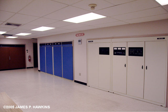
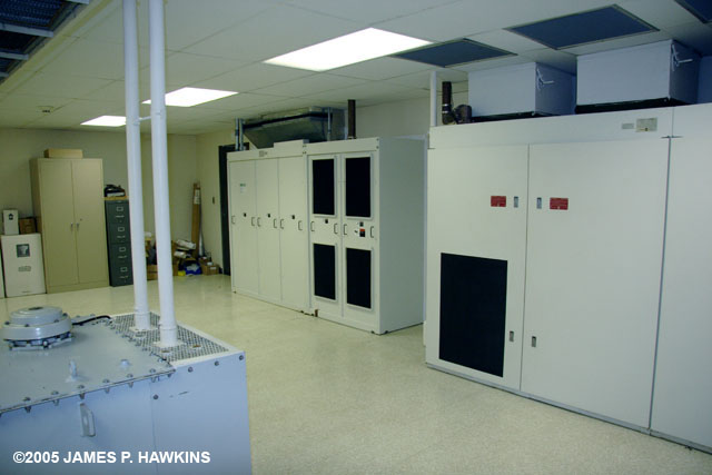
state, eliminating filament power (you can't heat the building on a cold day with a DX-50). The DX-50 takes the approach of using hundreds of small RF modules, stacked to add up to the total power output of the transmitter at any instant. To modulate the transmitter, the RF modules, each square wave amplifiers, are turned on or off in accordance with the modulating audio. The modulating audio control is accomplished by a set of solid state boards, which can all fit in a PC sized box. These boards convert the incoming analog signal to a digital representation, which, in turn passes through logic to control the output amplifiers. Each module is small enough to be held in your hand. All modules are coupled to a common buss via toroids to add up the total output power. The harmonics of the square wave are lost through filtration, leaving the carrier frequency and its sidebands. If one of the modules fails, the transmitter continues to operate at almost full power.

About 5 years ago, one engineer told me that he was saving about $9,000.00 per month by switching from the old plate modulated 50KW transmitter, to the DX-50. By this time, there are even more advances in transmitter design, allowing these solid state transmitters more flexibility in expansion and the automatic substitution of modules by spares if a failure occurs.

There are other manufacturers of efficient, solid state transmitter, which use slightly different, but efficient approaches. Nautel is one of them.

The DX-50 and newer transmitters lend themselves to a very simple hookup for expansion to HD (High Definition) modulation. The bigger difficulties may be in some output and antenna networks, but, often very little if any change is necessary.

WOWO started using HD on the AM band on April 4, 2005.

HD (IBOC) is further explained on my WOR page and the Harris DX-50 is further explained on my WABC NOW page.

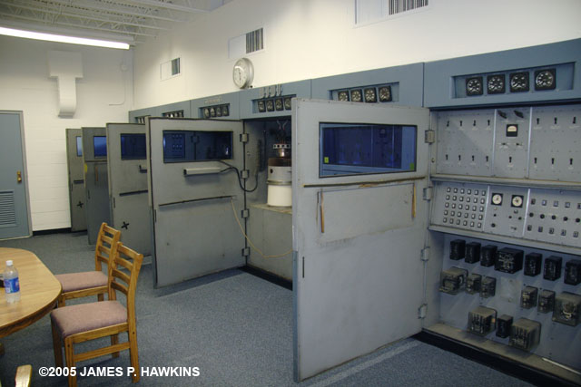
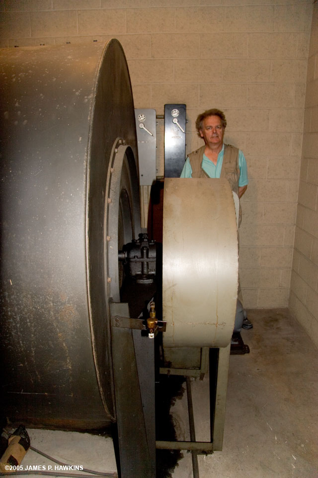
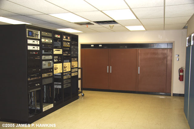
The one loss that has occurred with new technology is the AWESOMENESS of the large and roaring, engine-room feel and the Art Deco "56 Chevy Chrome and Glass" factor. Another change is that transmitter engineers and technicians maintaining these new, reliable transmitters, find themselves maintaining not one, but many sites. Their jobs have become regional with more travel involved.

...Jim Hawkins


Beacon from WMEE, Jack mounted
on some tower sections for display.


5671 Technical Specifications

Cathode (filament) 11 V 285 A.
Dimensions  25"L X 8.5"D
Amplification Factor 40


Class of
Service

Max. Freq.
for Full Input
Mhz

Max. Plate Ratings

Volts

DC Input Watts

Dissipation Watts

B

-------

15000

90000

25000

C-P

10

12500

55000

17000

C-T

10

15000

100000

25000


Class of
Service

Max. Freq.
for Full Input
Mhz

Typical Operating Conditions

Plate Volts

Grid Volts

Peak AF
Grid-to-Grid
Volts

Plate
Amperes

Plate-to-
Plate Load
Ohms

Approx.
Drive Pwr.
Watts

Approx.
Pwr Output
Watts

B -------

15000

-320

1600

10z

3320

600

100000

C-P 10

12500

-1500

-------

4

-------

1960

40000

C-T 10

15000

-1500

-------

6

-------

2040

70000

KEY

B
C-P
C-T
Superscript z
Class B Push-Pull AF Modulator Service
Class C Plate-Modulated Telephone Service
Class C Telegraph Service
Maximum Signal Value

5671 Physical Outline


Other notes:

  • The above characteristics were obtained from the publication: "RCA Power and Gas Tubes" 1959
  • RCA used the 5671 because they're were a huge number of them built for induction-heating service during WWII that became available as surplus toward the end of the war. [Mark Kriegar, a former CE of WKNR AM 1983-1990]
  • The later types have half as many cooling fins and are 225 lb., but, each fin on the new type have perforations for more effective cooling. The older type with more fins is 350 lb.
  • WGAR was the first station to use a transmitter with 5671 tube type
  • The 5671 tube history is rooted in the 1930s vintage 893 and 893-R. The internal structure of these tubes was modernized to develop the 9C21 water-cooled and 9C22 air-cooled counterpart. The 9C21 and 9C22 types were reworked by RCA to design the 5770 and 5671 respectively. An extensive historical treatment of the development of this tube can be found in an article by Ludwell Sibley: "The 5671," which can be found in the February 2001 edition of "Tube Collector" published by the "Tube Collectors Association." The article can currently be found online at the Tube Collectors Association website.

9C21


Image from:
The Encyclopedia Americana Vol. 23
1957 Ed.

Close-up of 5671 cooling fins
showing perforations for more
effective cooling.


Jack Didier and "Sidney," a female.


See WOWO Photos of Matt Kyle on Flickr - Terrific!

For WOWO history, click on "History" at WOWO official website.

Other Sources

WOWO Photos of Matt Kyle on Flickr - Terrific!
Reference.com
WOWO from Wikipedia - Historical Essay

For questions or comments regarding this page, please send e-mail.

©2005 Webpage Design, photos and attributed text - JAMES P. HAWKINS


PS: DARNED, I should have gotten a photo of "George" with the filaments on, but you can see that and get some other interesting information from Scott Fybush's WOWO Tower Site of the Week Page on his web site Fybush.com.

Accessed times since Nov 19, 2005

BACK TO "JIM HAWKINS' RADIO AND BROADCAST TECHNOLOGY" MAIN PAGE