|
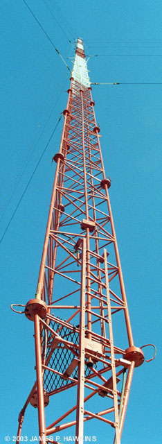
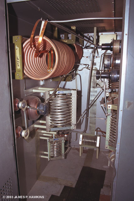
Looking up one of WOR's three |
Location Marker |
|
Looking up one of WOR's three |
Location Marker |
| WOR Announcement of increase to 50,000 Watts |
My own memories of WORAs a kid, WOR was THE place to tune for school closings announced by John
Gambling on a snowy day. When it snowed, my siblings and I would listen to Mr. Gambling as he read school after
school. It was like winning a day-off lottery. I also remember John Gambling Sr. with a live band in the studio. Visit the official WOR 710 web site for its current, diverse programming. |
|
|
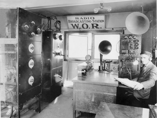
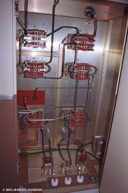
WOR pre 1932 Control and Transmitting room Source: Belden Photographers of Newark Supplied by Tom Ray - WOR |
|
|
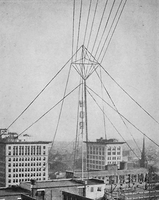
WOR Tower 1924 on top of Bamberger Station in Newark, NJ. Note transmitter house, shown in image above, appears bottom center in this image. Source: Radio News, January 1932 pp 566-568 Note: This photo was printed reversed in the magazine so that the "Bambergers" and "WOR" sign would read forward! |
|
|
|
WOR Transmitter Building in Kearny, NJ |
| Carteret transmitter building in 1935. Source: "electronics" Feb 1935 |
Carteret transmitter building layout in 1935. Source: "electronics" Feb 1935 |
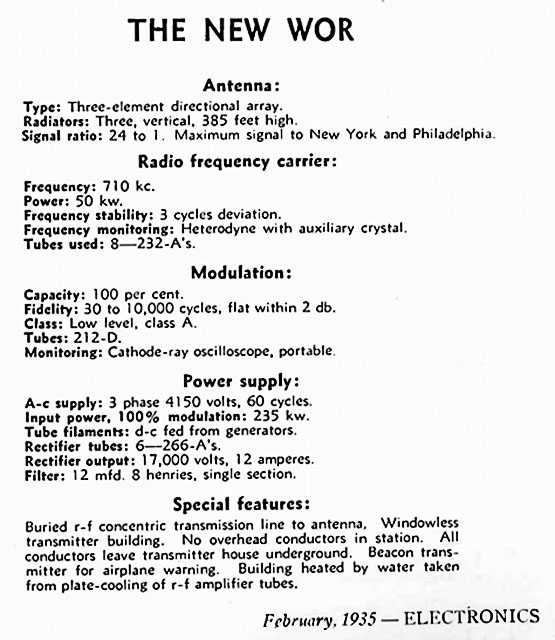 |
| Technical Information Source: "electronics" Feb 1935 |
|
|
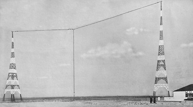
WOR Site as it appeared at Carteret, NJ in 1935. The two Blaw-Knox towers were 350' high. This system was an array of three vertical antennas consisting of the towers and the center wire suspended by the wire between the towers. The Carteret location was chosen to be in line with NY City, Trenton and Philadelpha. The three verticals were in phase to create lobes in the the direction of those cities. The weak end signals, were in the direction of the nearby NJ shore on the southeast side and the northwest PA mountains in the low populated Pocono area. See below. Source of photo: "electronics" September 1935 Source of information: "Commnication & Broadcast Engineering" February 1935 |
|
|
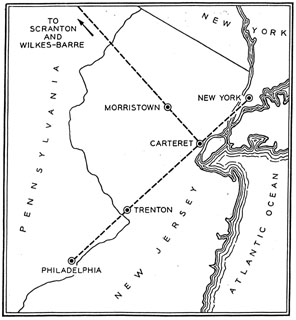 |
While at Carteret, the WOR transmitter was in line with New York, Philadelphia and Trenton and it's directional lobes were aligned to those cities. Source: "Commnication & Broadcast Engineering" February 1935 |
|
|
|
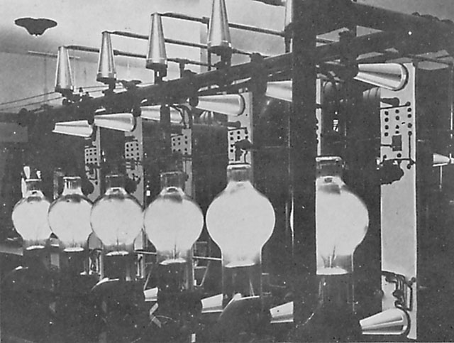
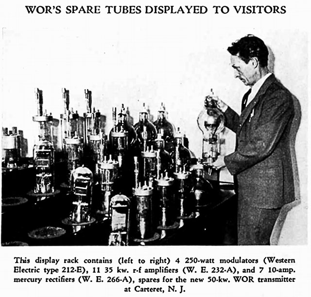
| Amplifier Tubes Source: "electronics" September 1935 |
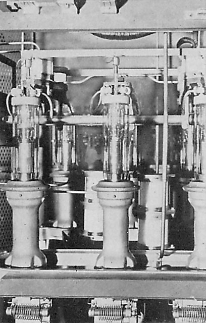
Mercury Vapor Rectifiers Source: "electronics" September 1935 |
|
These photos were used in am Isolantite Ceramic Insulator advertisement |
 |
| Source of photo: "electronics" April 1935 |
Magazine Links are to the library of www.americanradiohistory.com
 |
 |
|
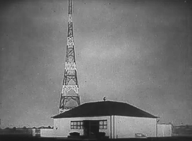
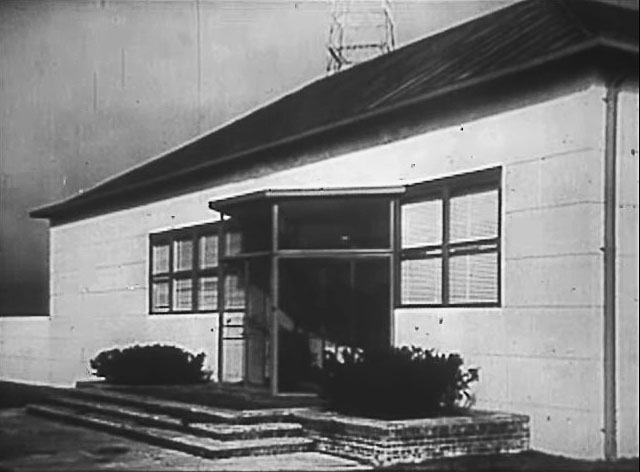
WOR Building screen grabs from Western Electric movie: |
|
|
|
|
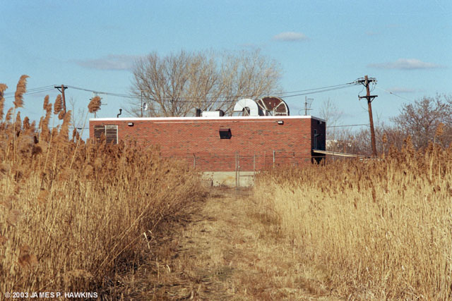
WOR Transmitter Building |
|
|
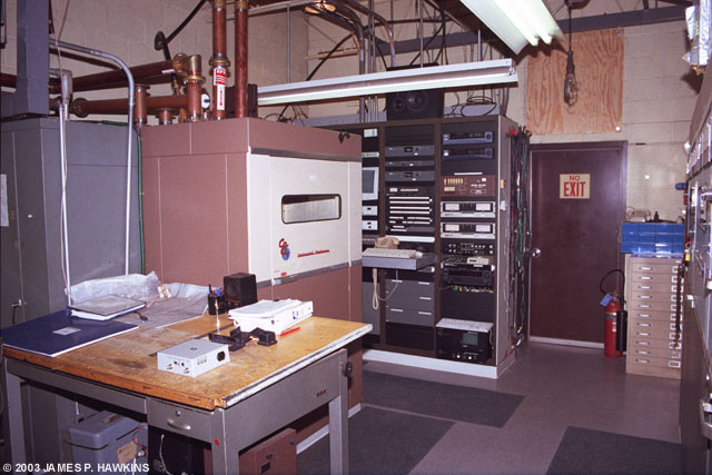
Auxiliary equipment racks contain satellite receivers, analog and digital audio processing and IBOC Exciter. |
| Many paths from the studios at 1440 Broadway. Input feeds rack, including satellite telephone line. |
 |
Digital (top) and analog processors Optimod 6200 (top) and 9200. The digital processor feeds the IBOC exciter.. |
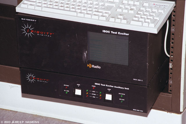 |
Ibiquity IBOC Exciter.. |
| The IBOC software runs on a Linux OS platform. The unit can be controlled remotely via dial-in modem. It also has a TCP/IP port. The IBOC exciter box has a GPS receiver to synchronize all IBOC transmitters for quick tuning and lock-in from one HD station to another. |
|
|
|
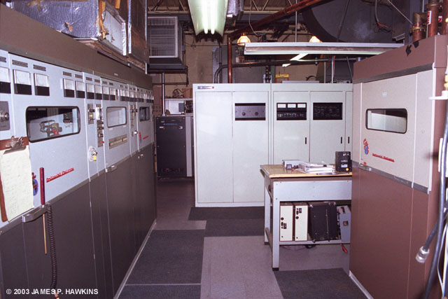
| Left: Continental 317C-1 on left, Harris DX-50 Main transmitter at the far end and RF Switching cabinet on the right. Right: View from opposite end showing RF Switching and auxiliary equipment racks behind it. |
|
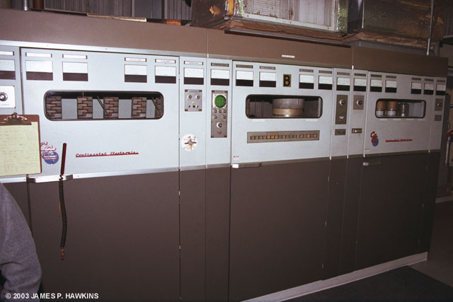 |
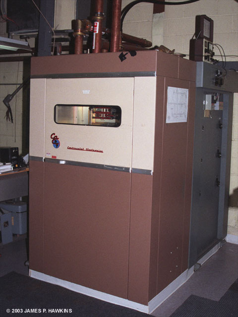
The Continental 317C-1 is a Doherty linear tube transmitter. It serves as a standby transmitter and is used once per week for the Joe Franklin show on Sunday morning, midnight to 5:00 AM. Joe Franklin not only still has his radio show, but his own restaurant and, in a way, his own transmitter! |
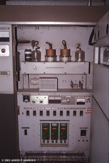 |
Door open on 317C-1 Driver cabinet reveals 3CX3000As. |
|
|
|
|
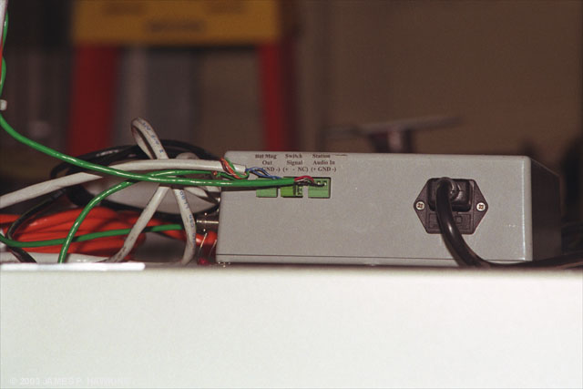
IBOC Junction Box |
IBOC Junction Box on top |
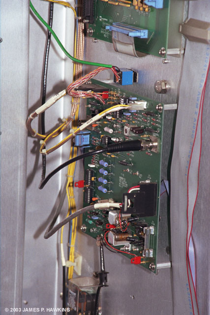 |
Exciter (blue) relay to switch from internal to IBOC is mounted between the two boards. |
| The IBOC system is connected into the Harris DX-50 with fail-safe mechanisms installed. The connection from the internal exciter to the first driver was replaced by a relay, which switches to the IBOC exciter. The Audio is also switched from pure analog processor the output of the IBOC exciter. If the IBOC system fails, it is detected and the relay switches from the IBOC exciter to the internal RF and the analog processor. |
|
|
RF output switching cabinet connecting with the phasor behind it. |
|
|
Inside the RF switching cabinet. It feeds the three towers, switches between the two transmitters and switches the dummy load. It allows single tower operation with any of the three towers. Switching to low power non-directional allows maintenance on other towers and the phasor. It controls the common point input to the phasor and the 3 outputs of the phasor. |
|
|
The phasor front panel. |
|
|
Inside the phasor looking in through the back door. The IBOC carriers could be heard "ringing" the coils as a hissing sound along with the analog audio in this cabinet. New coils were installed in 1998. |
 |
The tower array is in a dogleg (weak triangular) configuration. Each tower has detuning skirts for 1010 (upper) and 1190 KHz. Click on the images for a better view of the skirts. At the bases are detuning networks for 1010, 1190 and 620 KHz. |
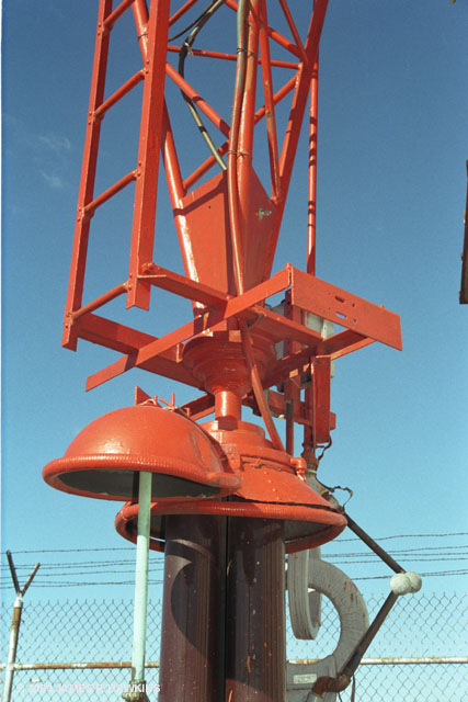 |
Tower base showing Austin transformer, "Johnny Balls" to divert lightning strikes. |
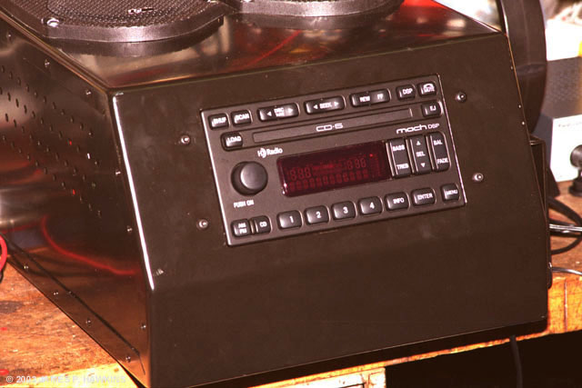 |
| Kerry demonstrated the WOR-HD with this receiver to me. First he tuned in some other AM stations, which, of course sounded like the usual narrow bandwidth AM. Then he tuned in WOR. Initially it sounded like the other stations, but within about 2 seconds it opened up with a very clear, High Fidelity sound. The transition sounded as if the radio had been in a box and the lid had been taken off. I was told that with the initial IBOC exciter software the sound was good, but, with each new exciter software update, the audio has continued to improve. One cannot make a final judgment as this system is continuing to evolve and improve. |
 |
|
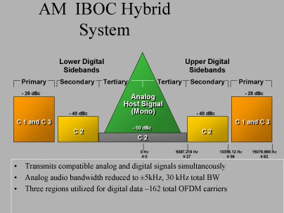
The IBOC AM Hybrid signal consists of
In the IBOC AM all digital mode, |
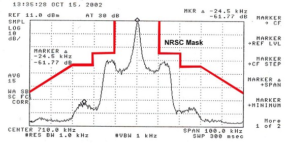 |
| The WOR-HD spectrum shows the carrier in the center, the two "valleys" on either side are the secondary digital regions and the first set of peaks show the primary digital carrier regions. The red outline show the NRSC Mask, which bounds the legal limits of the overall hybrid signal. |
|
 |
300KW 3 phase 440V Generator. |
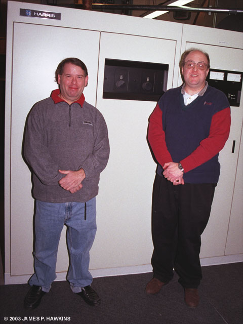 |
Kerry Richards, Chief Engineer (Left) and Thomas R. Ray, III, CSRE, and Corporate Director of Engineering Read Tom's article in Radio World |
as described by Tom Ray
Emphasis and formatting added by Jim Hawkins
|
If the main transmitter is operating in analog mode, the audio chain is:
This switching is remote controllable. The chain for the main TX is as follows:
The analog audio modulation is set, with IBOC carriers off, to -98%/+120%. This modulation does not change.
The primary and secondary carriers then modulate the transmitter to produce sidebands where the primary IBOC carriers
are -28dB referenced to carrier level [-28 dBc], while the secondary IBOC carriers are -38dB referenced to carrier
[-38 dBc]. Total digital carrier power is approximately 1500 Watts for a 50KW station. |
| Accessed | times since February 2, 2003 |
© 2003 by James P. Hawkins
![]()
|