|
|
Jim Hawkins'
|

Location Map
|
|
Jim Hawkins'
|
Notes on WSAI operationsby J. T. Anderton VP/Managing Director of Duncan's American Radio WSAI went from a three-tower to a four-tower array in the late 1970s. The old pattern had favored skywave coverage of the South. The station modified the array to throw more power over the more heavily populated parts of the Cincinnati metro area, which are to the north and east of the towers. There are only about 350,000 people in the part of northern Kentucky adjacent to towers, while there are
about 1.5 million people in the metro on the Ohio side. The pattern modification required adding a fourth tower,
and the relocation of two of the three then-existing towers. They opted to build three new ones instead of moving
two and adding one. The 350' tower which WSAI currently uses in non-directional mode is the only one of the three
original towers remaining. Another interesting fact about WSAI is that it operates in non-directional mode until Sacramento sunset (it protects channel-mate KFBK), which is three hours after sunset in the Eastern time zone. This results in a nice early-evening skywave in many parts of the Midwest which lose the signal after WSAI hits pattern. |
| Click here for WSAI jingle--> Sorry about the inferior quality. I need a better converter. |
|
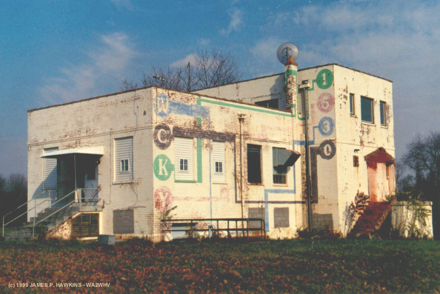
| Chief Engineer, Jim Ranny speaks about WCKY Thanks to Peter Peterson for supplying this clip. |
|
|
|||
|
|
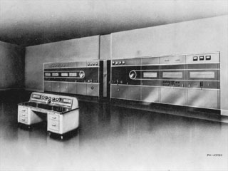 |
| This model transmitter was used at the site, which was then, WCKY between 1938 and sometime in the early 50s. This picture is from a 50-D manual. It used low level modulation into a variation of the Doherty linear, which became very popular in Continental Electronics transmitters. It used a pair of UV-898s (3 phase filaments) which were later replaced by UV-862 (single phase filaments) water cooled tubes, one for the "carrier" tube and the other for the "peak" tube. These tubes were also used in the WLW 500KW transmitter. At WCKY, the final amplifier was, later modified using 5681 tubes for the carrier and peak tubes. |
 |
 |
|
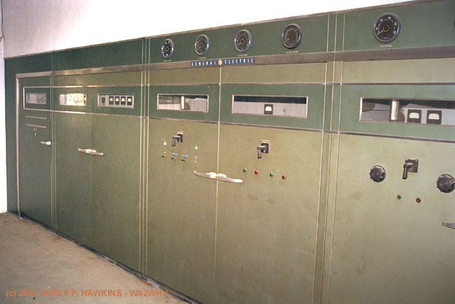
Left end of BTA-25-A |
Right end of BTA-25-A |
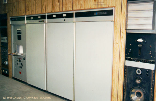
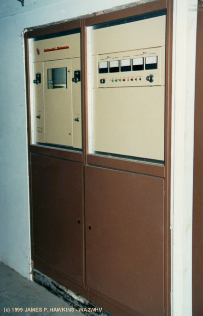
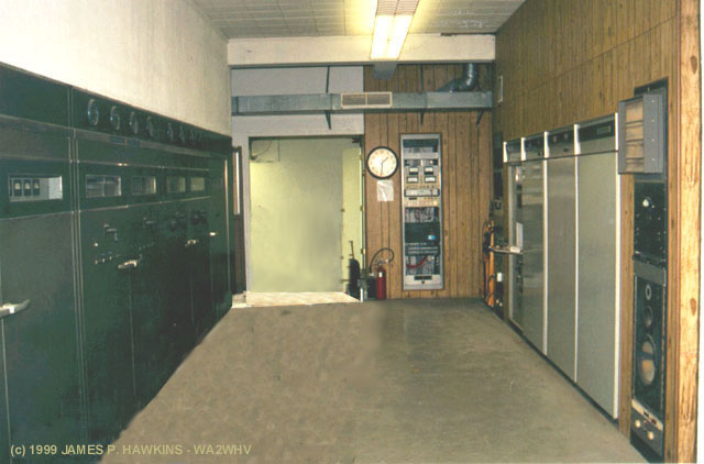
| The BTA-25-A is a very long transmitter, making it very difficult to photograph in the narrow space available, hence the two views. The right view actually shows all modules or cabinets. From left to right are the control unit, tank circuit and output network unit (two cabinets wide), RF final amplifier (two cabinets wide), high level plate modulator (two cabinets wide) and full wave three-phase HV power supply. This transmitter is no longer in use with all components containing PCBs having been removed. The transmitter plate voltage was approximately 10KV at a DC current of about 6 amperes. |
 |
|
Large Round Meters |
 |
 |
|
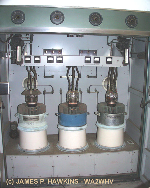
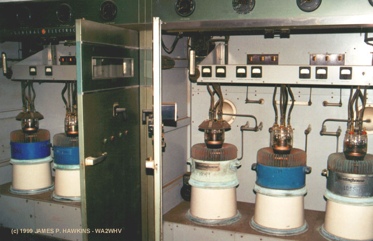
Modulator |
PA and Modulator - doors open |
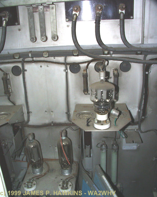
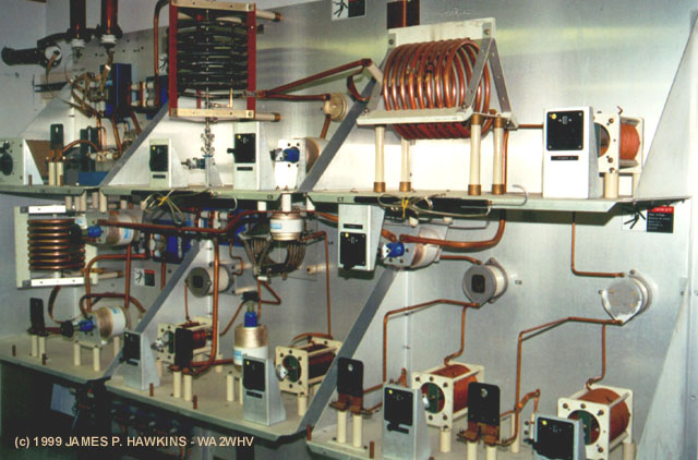
| The PA and Modulator, each use a pair of WL 5891 air cooled tubes. The third (center) tube in each cabinet is a "hot" spare which can be quickly jumpered in should either of the others fail. In the modulator cabinet it is easy to see the movable jumper bars against the back wall of the cabinet. This permits fast tube change during critical broadcast periods. The defective tube, weighing over 100 lb., is then hoisted out of the cooling chimney and replaced using a special hydraulic lift designed to fit the tube during a less critical part of the broadcast day. I believe, each of these tubes are driven by a 304TL triode in back of the separating wall. |
 |
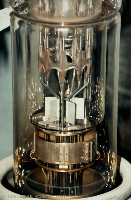
Close-up of 5891 sitting in porcelain chimney from which forced air passes up through the metal cooling fins. |
 |
Close-up of the top glass part of the tube showing the tube markings. |
 |
304TL Driver to a 5891 as seen from the back of the cabinet. |
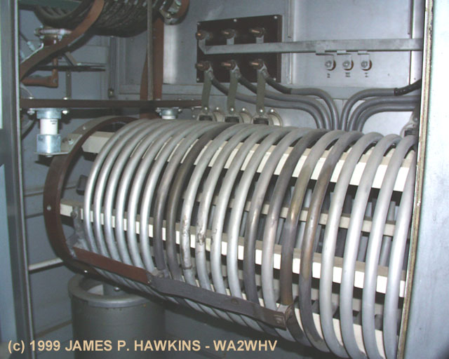 |
Tank circuit as viewed from the back. Notice the variable tuning capacitor below the coil (bottom left). |
|
|
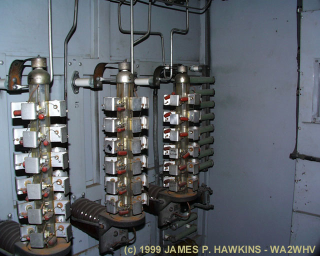
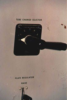
The power supply consisted of 7 mercury vapor rectifiers (before conversion to solid state). Six of the seven were used for full-wave rectification of a three-phase AC voltage. The seventh tube was a spare which could be used to replace one of the six if a failure occurred by rotating the switch shown at left to the number of the failed tube. An indicator showed which tube failed. |
|
|
Shown is an AC voltage regulator which works on the principle of motor driven variable coupling. Just below the rectifier change switch (above) is "plate regulator" switch. When pushed up or down, this switch causes the voltage regulator transformer to seek to the desired regulation point. |
 |
Solid state rectifier stacks which replaced the mercury vapor rectifiers. The conversion from mercury vapor rectifiers to solid state replacements seemed to have been done on old transmitters without delay as mercury vapor rectifiers could be very troublesome. |
|
|
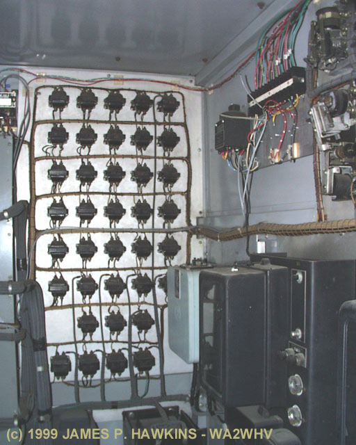
There is a separate transformer for each control indicator light. This is also done on the GE XT-1-A, which is the same vintage 1KW little brother. GE was also known to have a separate meter for every readable parameter as opposed to some other makes which used multi-function meters. |
|
|
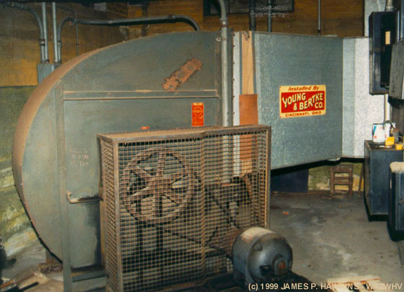
| Huge, 6' tall blower used for the GE transmitter. The electric Motor is 7.5 horsepower. |
 |
WSAI Standbye transmitter is a Harris MW-50 Pulse Width Modulated transmitter. |
 |
Plate transformer for MW-50 (in basement). |
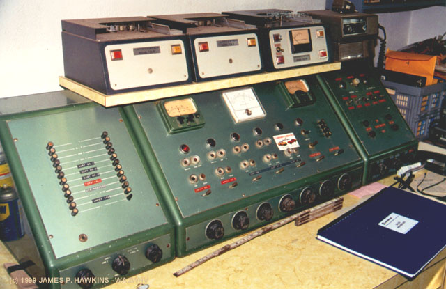 |
This is a home brew passive (no amplification) audio console/mixer. It was used for programs which used to originate from the transmitter site at night. |
|
|
Audio processing equipment, including AM Optimod. |
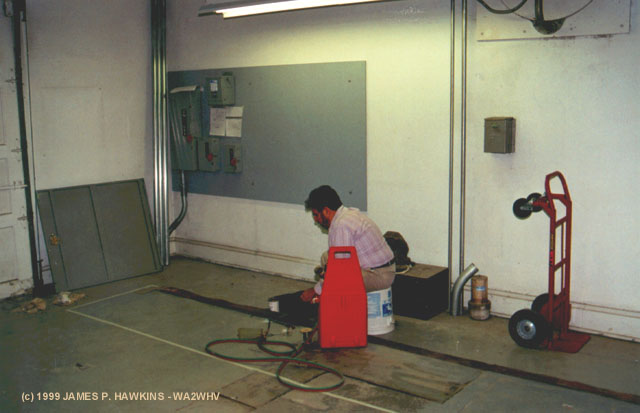 |
In this photo, CE, Ted Kendrick is welding ground strap which now runs along the bottom of the Harris DX-50. In the picture, note, the tape on the floor which outlines the small footprint where the DX-50 was to be installed. The unit arrived as I was leaving. |
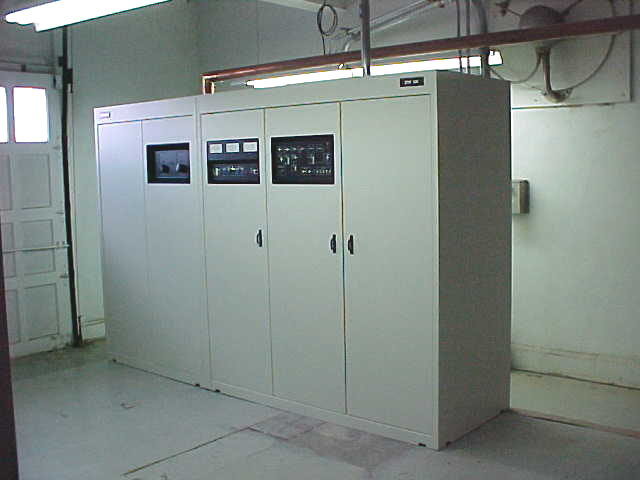 |
The DX-50 is now the main transmitter with the MW-50 as the standby transmitter. This picture was taken by Paul Jellison and received 3/4/2000. |
 |
New phasing circuit built on the wall of the room next to where the DX-50 is installed. |
| Accessed | times since November 19, 1999. |
![]()
| Fine Print: All images are Copyrighted and are provided for your personal enjoyment. Use of these images for commercial purposes including their distribution on CD-ROM or any other media without my permission is prohibited. |

