WLW 500KW Transmitter Schematic
(Jim Hawkins' WLW Transmitter Page)
Accessed  times since August 21, 1999.
Thanks to Harold Parshall N8FRP for supplying this schematic!
The schematic was in a article about the 500 KW transmitter borrowed from a former WLW engineer who worked there
during the 500KW days.
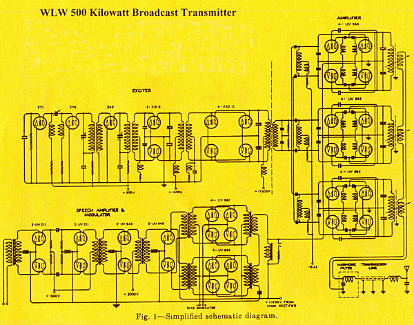
500 KW TRANSMITTER DESCRIPTION IN A NUTSHELL
The transmitter was designed with redundancy and cutback (reduced power mode) in mind, giving the transmitter
more continuity of service. The final amplifier was divided into 3 separate modules, each using four RCA type UV-898
tubes in push-pull parallel making up a total of 12 output tubes. The outputs of the three modules were combined
in series in such a way, that if one of the 3 RF modules failed, the transmitter could continue to operate using
the other modules. This idea was a very important step in transmitter design as modern solid-state transmitters
are designed entirely in this a modular fashion as is described in my WABC Digital AM Transmitter Page Digital
Modulation Section. Modern transmitter with modular design are composed, typically of 1KW modules with
lower power modules used for shallow slopes of modulation.
In the same fashion, the 8 tubes in the modulator were actually 2 modules composed of 4 tubes in push-pull parellel,
each with a separate modulation transformer, making it possible for the transmitter to continue to be modulated
at a reduced level if one of the modules failed.
The power supply section (on the rightmost end of the transmitter) used six mercury vapor rectifiers each rated
to handle 450 amperes. These tubes can be seen in a 1930s photo on my WLW brochure page.
The operating Constants recorded in the log for the 500 KW transmitter on May 2, 1934 were:
PA voltage of 11.7 Kilovolts with a PA current of 65 Amperes, which yields a DC input power of 747.5 KW.