JIM HAWKINS'

WLW
Revisited


A closeup of one of the UV-862 100KW tubes after wiping it down with cleaner. The intricate detail is clearly visible. This top glass section is about 18" tall. The non-glass bottom section extends about 4' down into a water cooling jacket. (Click on picture for larger version.)


New Antenna System

The Blaw-Knox "diamond" has
company. New 1/4 wave "stick"
installed 1998 at left.

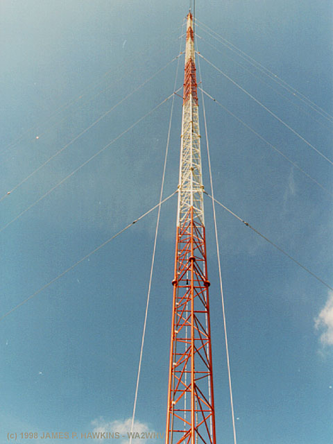
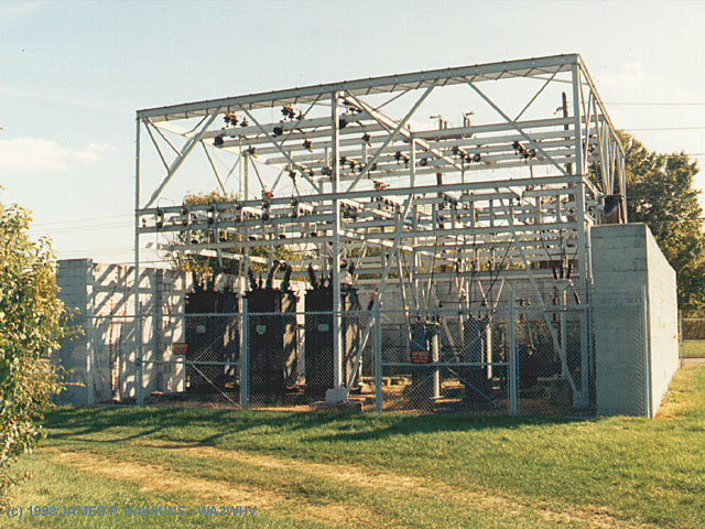
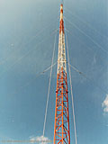
Looking up at the new standby
tower which is a 1/4 wave, shunt fed,
folded unipole.
Space may be leased for other use on
this grounded tower. The antenna system was designed
by
du Treil, Lundin & Rackley, Inc.

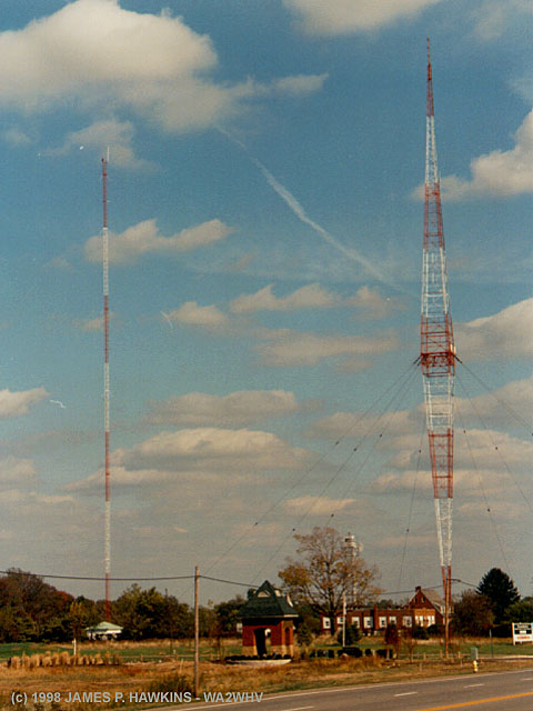
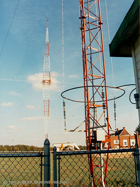
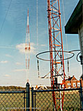
A view of the bottom of the new tower
showing the details of the unipole lower
construction and the old WLW diamond
tower iin the background.

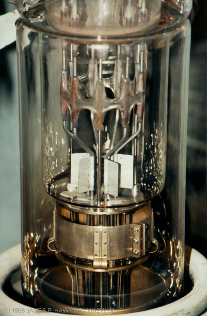
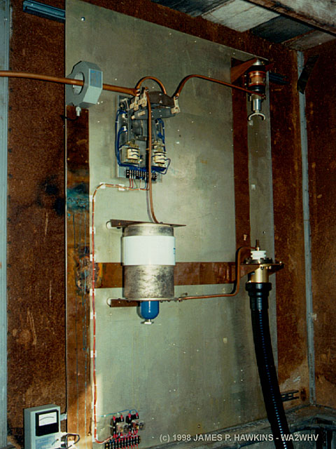
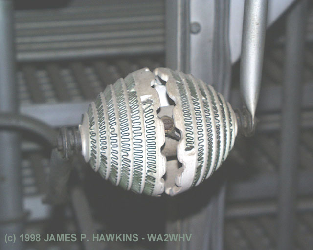
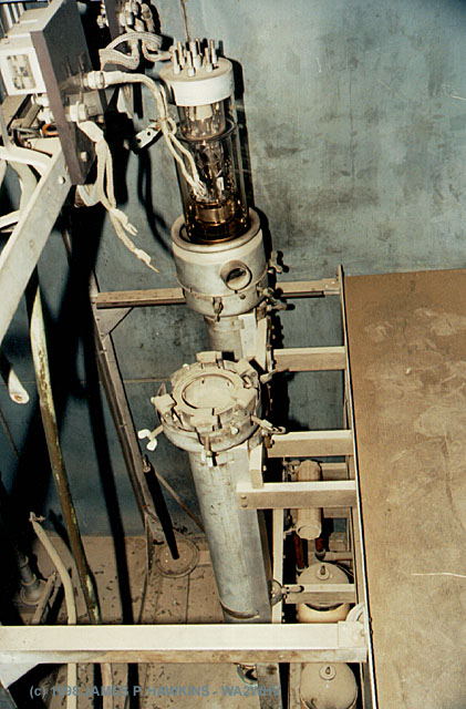
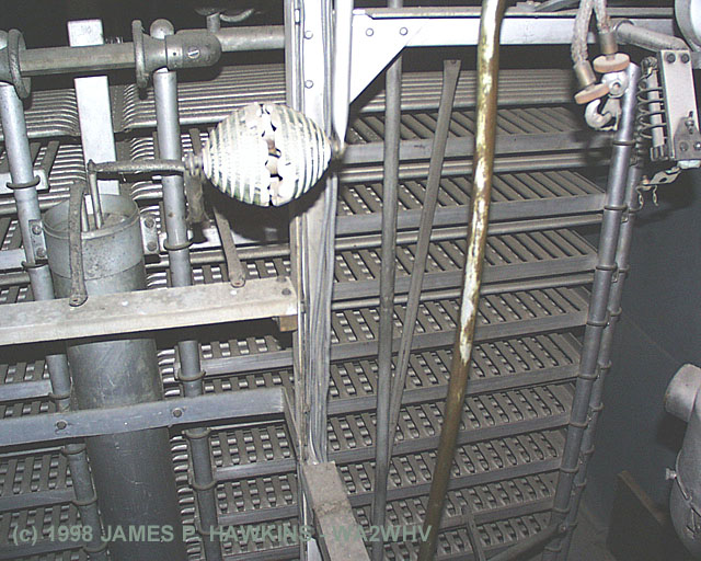
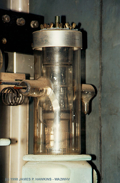
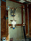
Inside the tuning house, a single large vacuum
capacitor (white object in center) cancels the
inductive reactance of the tower. The tuning house
was built in 1928 and is actually the original tuning
house used before the Blaw-Knox diamond was erected.
The smaller vacuum capacitor at the upper right is for
detuning, obtaining a 30db reduction in re-radiation.

As an aside, because of the construction of the vacuum
cap, you can actully hear it "sing" to the picked up RF
from the main tower. It acts like an electrostatic speaker.

New Antenna/Transmitter Switch

New switching control rack allows
any transmitter to be connected to any
tower. The unit can also be remote
controlled.

Back of switching control, skillfully
wired and laced by Jacor CE
Ted Kendrick, who is responsible for WSAI.

The actual antenna switches are located
in the back room where the old 500KW
transmitter is located. It allows any of the
four transmitters to be connected to either
of the two towers.

Substation

WLW Substation (3 phase)
Torn down since this photo
was taken.


The Book!

PICTURES

TEXT

THE MANUAL

This is the one and only manual
for the WLW 500 KW transmitter
(that I know of). Click on the book
image to get an excerpt of the text
description and LOTS of pictures
of the 500 KW transmitter.


More 500KW stuff.


Egg Shaped Resistor

Looking down
into an RF unit.
Tubes and tube
jackets extend
4' downward.

The "baking rack" looking
thing in the back is one of
the three output tank
capacitors.

Modulator tube


Accessed times since October 20, 1998.

Fine Print:
All images are Copyrighted and are provided for your personal enjoyment. Use of these images for commercial purposes including their distribution on CD-ROM or any other media without my permission is prohibited.

Contact: Jim Hawkins


Back to Main WLW Page